, and Tanzu")
NSX Application Platform Part 3: NSX-T, NSX-ALB (Avi), and Tanzu
NSX-T Logical Networking, Ingress, Load balancing, and Tanzu Kubernetes Grid Service (TKGS)
This article will elaborate on the logical networking component of this deployment, which was introduced in Part 1. It will cover the configuration in NSX-T and NSX Advanced Load Balancer (NSX-ALB/Avi), specifically for the deployment of NSX Application Platform (NAPP). Finally, it will conclude with the deployment and configuration of Tanzu Supervisor and workload clusters.
I have recently put together a video that provides clear guidance on deploying NAPP, it can be seen here.

NSX Application Platform (NAPP) // NSX Advanced Load Balancer (NSX ALB)
Understand NSX Application Platform (NAPP) architecture and how to deploy it using NSX Advanced Load...
Note: This article will not walk through the deployment of NSX-T or NSX-ALB (Avi).
NSX-T Networking
I briefly touched on the two networking options when deploying Tanzu: NSX-T and vCenter Server Networks.
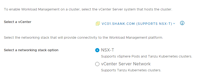
NSX-T: Using this option will instantiate the logical networking components required for the deployment in NSX-T. This includes a Tier-1 gateway, overlay segments for Ingress, service, egress and VIPs. The VIPs are created in NSX-T’s native load balancer.
vCenter Server Network: Using this option requires the administrator to select existing vCenter VDS Portgroups. However, it also means the administrator has the option of selecting NSX-ALB (Avi) or HA Proxy for load balancing and VIP creation.
This deployment utilizes the vCenter option, which will be covered later, however, the VDS portgroups selected are actually NSX-T Overlay networks, so that I can still leverage some NSX goodness.
NSX-T Segments
The screenshot below shows the same 3 segments displayed in the diagram in part 1 of this series.
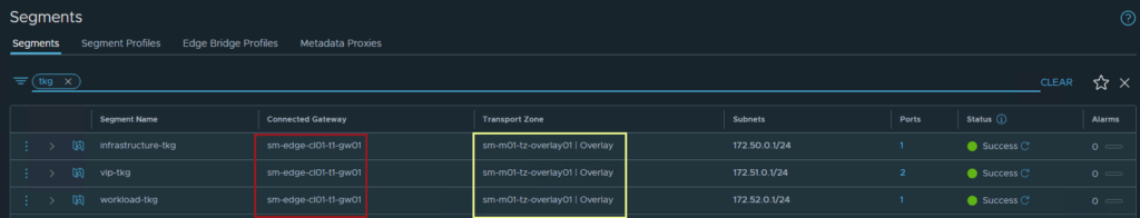
All three segments are connected to the same Tier-1 gateway “sm-edge-cl01-t1-gw01” and overlay transport zone “sm-m01-tz-overlay01”. Because the segments are connected to a Tier-1 gateway, it is implied that they are overlay networks and will utilize NSX-T logical routing. This is because VLAN backed segments cannot be attached to a Tier-1 gateway.
NSX-T Gateways
Tier-1 Gateway
The screenshot below shows the configuration of the Tier-1 gateway.
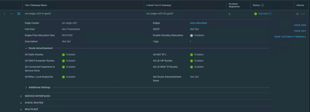
The Tier-1 gateway configured in this example has all route advertisement options enabled, however, this is not required for the deployment. At a minimum, as long as segment prefixes are being propagated to the linked Tier-0, that is all that is required, the option “All Connected Segments & Service Ports” will be enough for this.
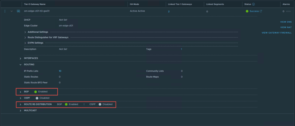
Tier-0 Gateway
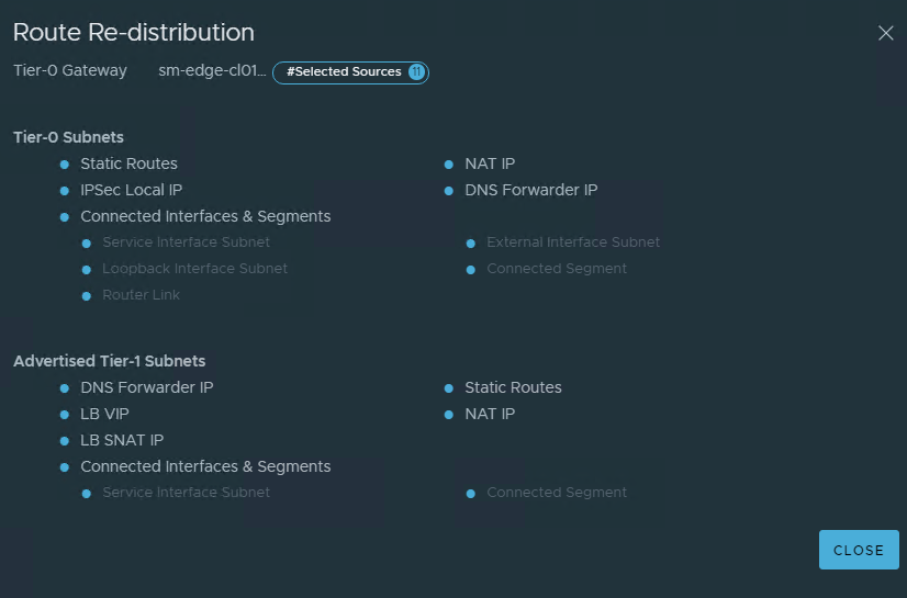
The Tier-0 gateway will be responsible for making the networks available to the physical network, in this case BGP is used, however, you may use static routes or OSPF. The screenshots below display the basic configuration required on the Tier-0 gateway, similar to the Tier-1. At a minimum “Connected Interfaces & Segments” will need to be enabled for route re-distribution.
The next section details the NSX-ALB (Avi) configuration, and some basic traffic flow between the NSX-T segments and NSX-ALB (Avi).
NSX Advanced Load Balancer (NSX-ALB/ Avi)
This section will focus on the minimum viable configuration required for the successful deployment of NAPP and Tanzu. I have assumed that you have assigned a license to the NSX-ALB controller, and hence will not cover this.
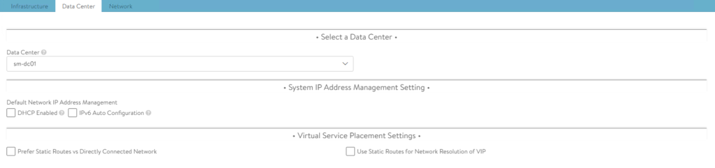
NSX-ALB Default-Cloud Configuration
Ensure you configure and use the Default-Cloud object in NSX-ALB. This is currently the only supported cloud type for this deployment. For more information click here.
The following screenshots show the configuration of Default-Cloud in my environment.
Note: The difference between read and write access modes can be found here.
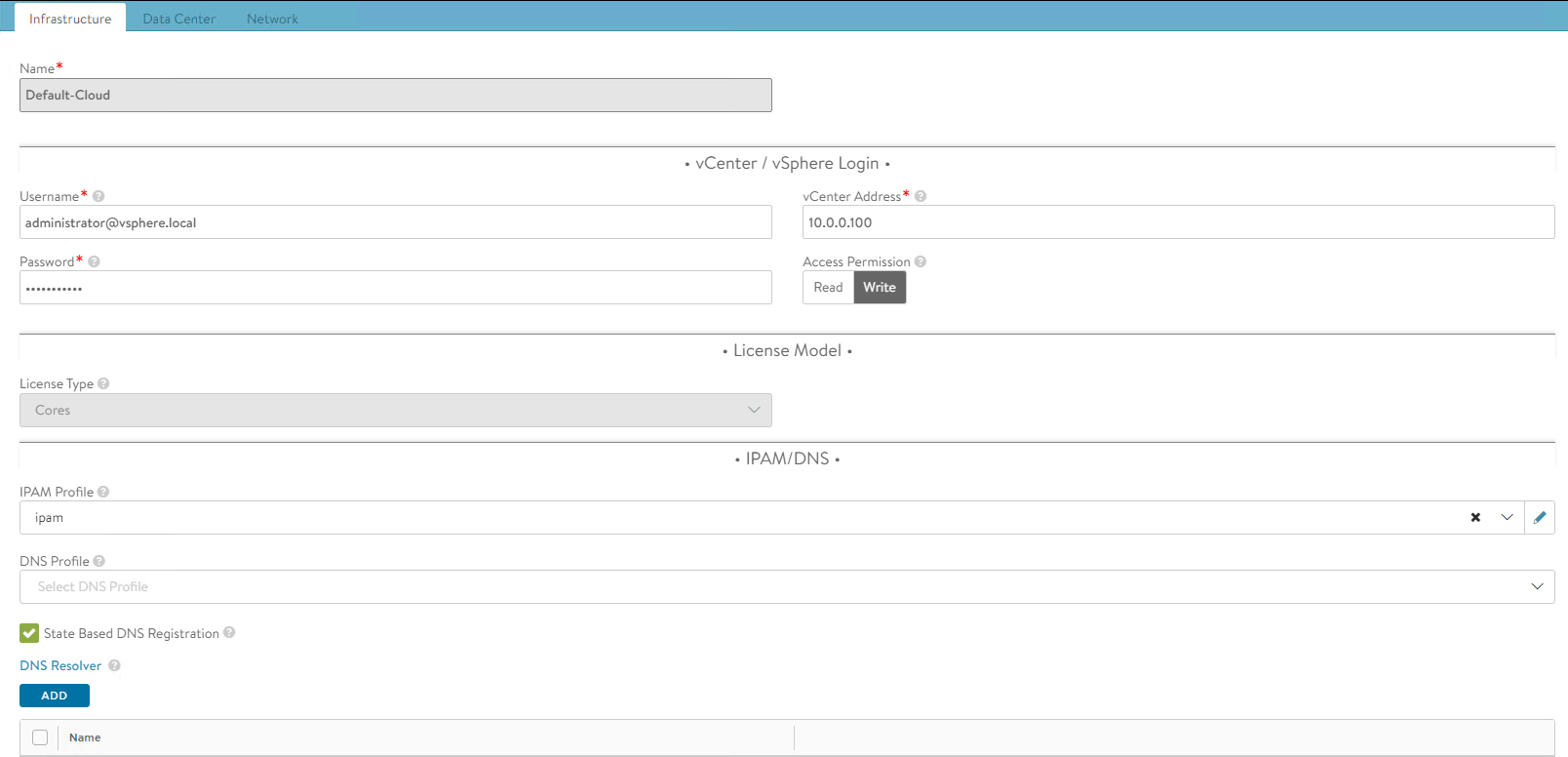
The IPAM profile will be covered in one of the following sections.
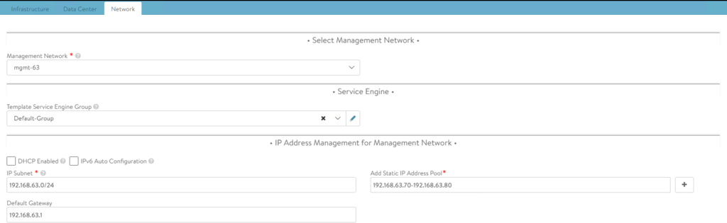
Notice the network defined for management access is VLAN63, which is a simple VDS portgroup tagged with VLAN 63.
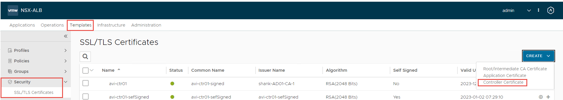
NSX-ALB Controller Certificate
This section details the steps to configure the controller certificate, which is sent to clients for secure connections. The default controller certificate cannot be used as the default generated does not have the correct SAN entries.
- To configure a certificate select Templates -> Security -> SSL/TLS Certificates -> Create -> Controller Certificate
2. Fill out the details relevant to your environment in the screen below.
Note: If you are running a cluster of NSX-ALB controllers, ensure you enter the FQDN and VIP for the cluster under SAN entries.
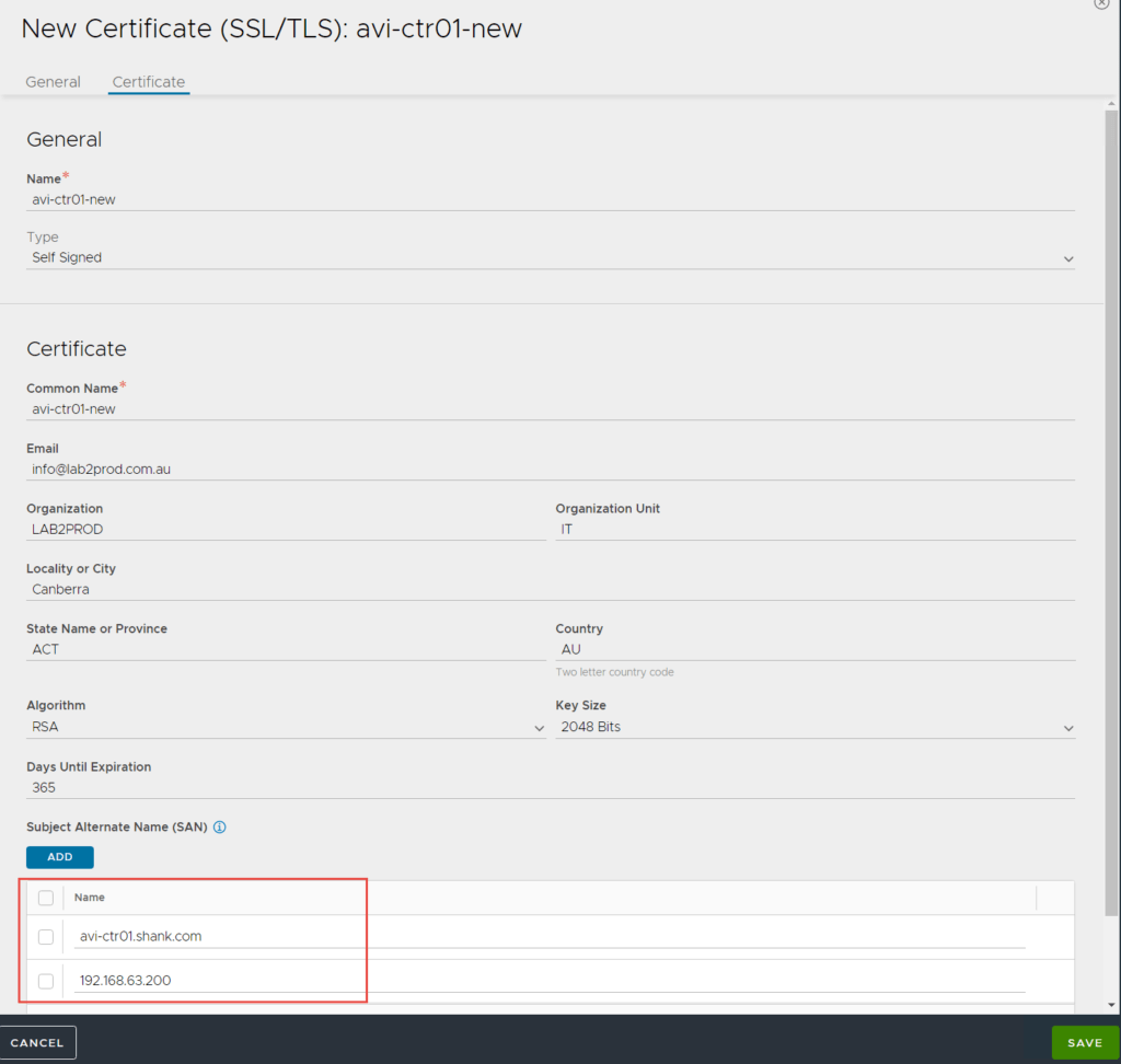
3. Click Save once complete.
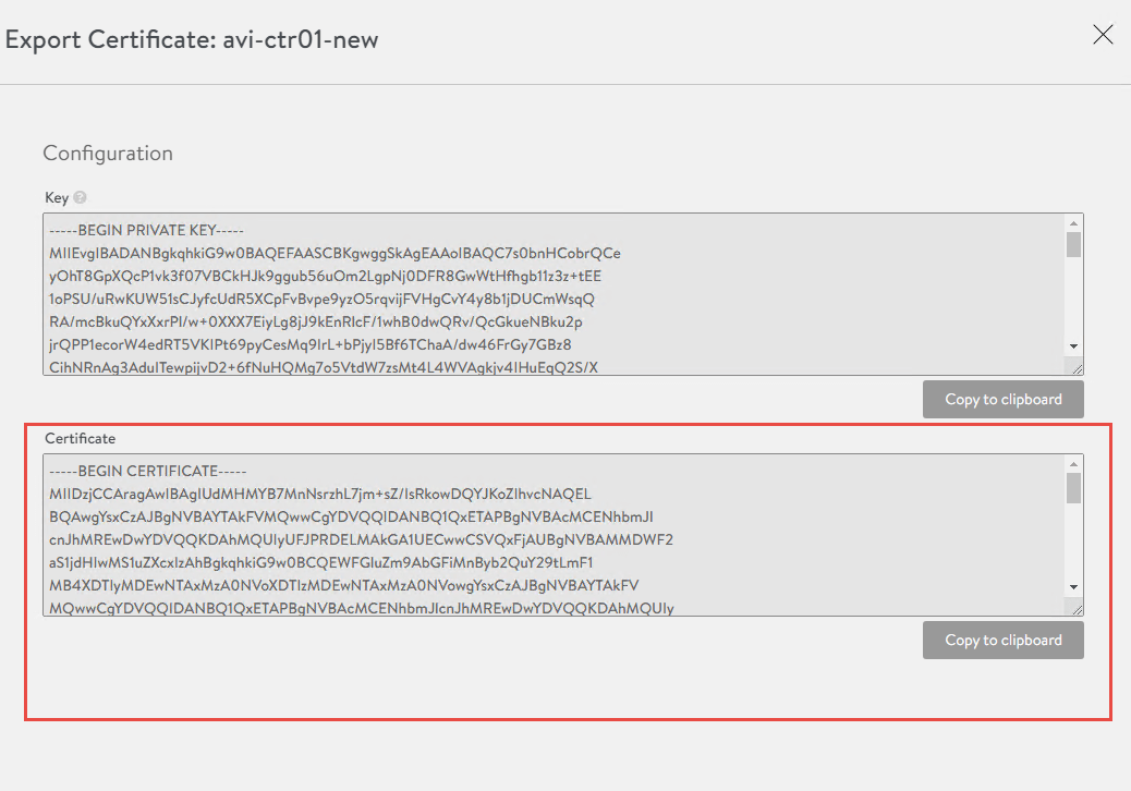
4. We will need this certificate in a later step, so in the below screen click on the little down arrow next to the certificate and copy the certificate to notepad.

5. Next we need to assign this certificate as the SSL/TLS certificate used to access the NSX-ALB control plane. To do so click on Administration -> Settings -> Access Settings -> Edit
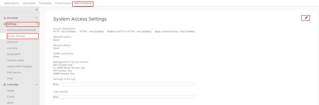
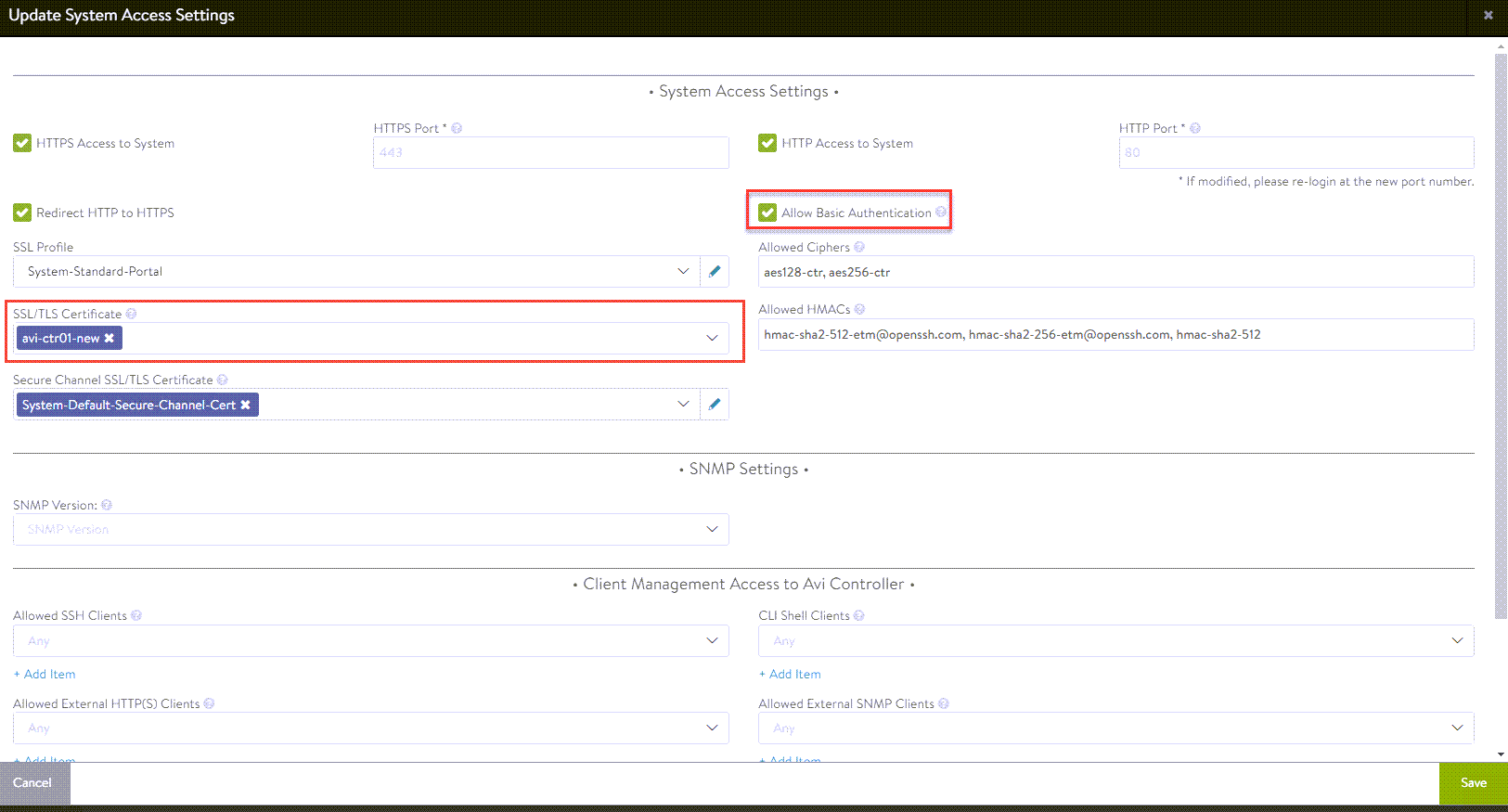
Note: ensure “Allow Basic Authentication” is selected or else the deployment of the supervisor cluster will fail with authentication issues. Special thanks to Victor Monga for pointing this out!
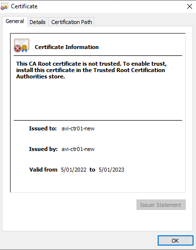
6. Click Save once complete, once you do, the certificate is applied and you may notice yourself get kicked out and having to sign back in. Check to make sure the certificate was applied.
Service Engine Group Configuration
Usually I keep these settings as default. The only change here was to include the cluster where I wanted the Service Engines deployed.
- To configure this, click on Infrastructure -> Cloud Resources -> Service Engine Group -> Edit Default-Group.
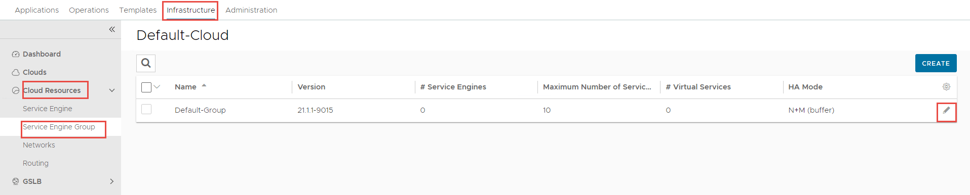
2. Select the Advanced tab, click Include and select the cluster.
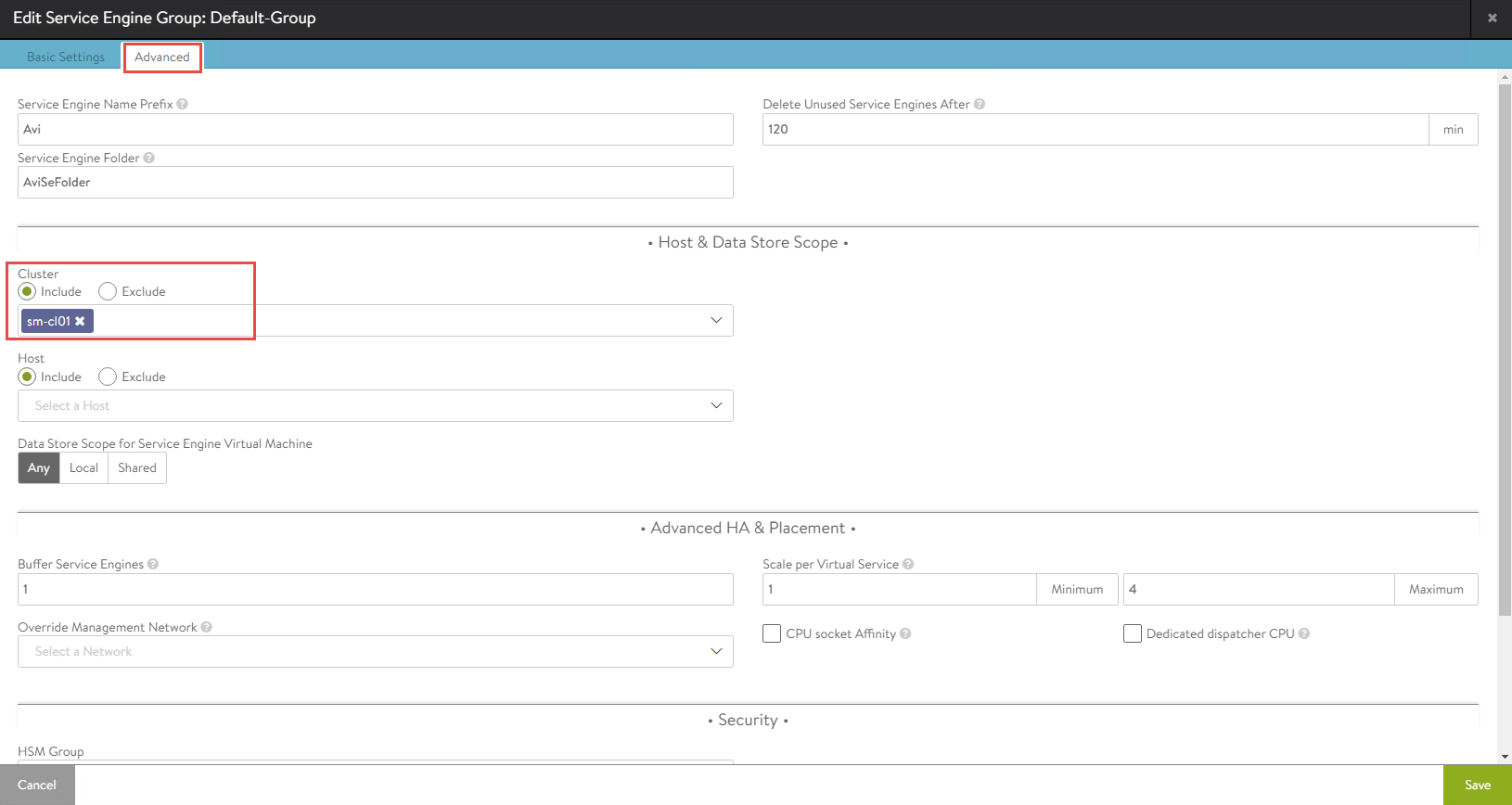
3. Click Save once complete.
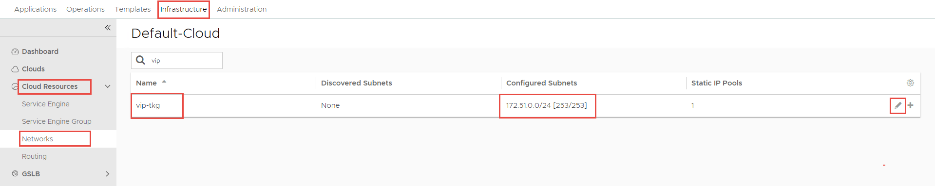
Configure the VIP Network
In this section, we will define the VIP network in NSX-ALB. In Part 1, there was a segment called “vip-tkg”, with the prefix 172.51.0.0/24. This is the subnet we are going to define as the VIP network in NSX-ALB.
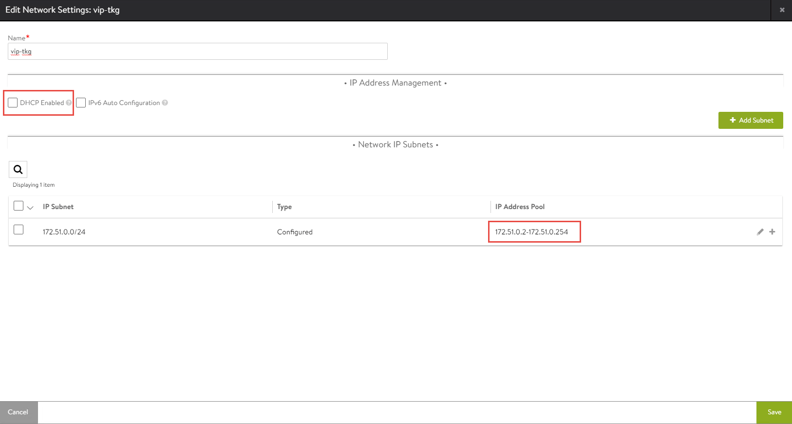
Navigate to Infrastructure -> Cloud Resources -> Networks, find the network you will be using as the VIP network and click Edit.
The following screenshot is the configuration applied in my environment. DHCP is not required as NSX-ALB’s IPAM service (which we will configure) will assign VIP addresses as required.
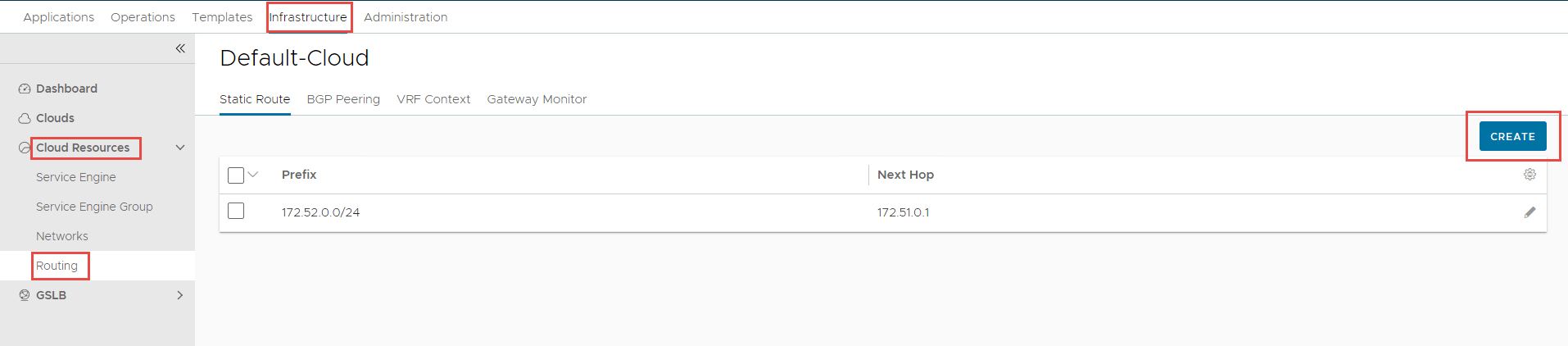
Static Routes
A static route is required (unless you are using dynamic routing) to allow connectivity from the VIP network to the workload network. In this case, it will create a routing table entry on the service engines to tell them how to reach the workload-tkg (172.52.0.0/24) network.
To create the static route, navigate to Infrastructure -> Cloud Resources -> Routing -> Click Create.
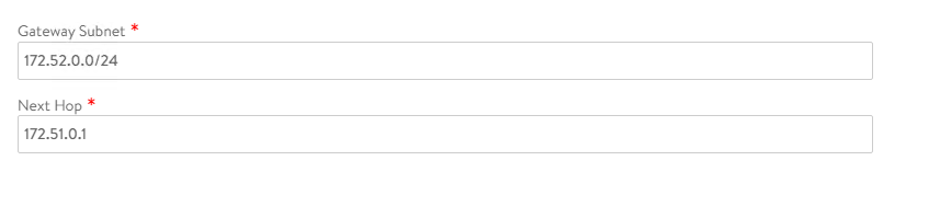
Click Save once complete.
IPAM Configuration
The IPAM profile is required for VIP address assignment. Without this, when the TKGS setup workflow and subsequent NAPP pods request an external or ingress IP address, they will not receive one, and the deployment will fail.
To create an IPAM profile navigate to Templates -> Profiles -> IPAM/DNS Profiles -> Click Create.
The below screenshot shows the configuration of my IPAM profile.
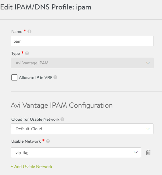
Click Save once complete.
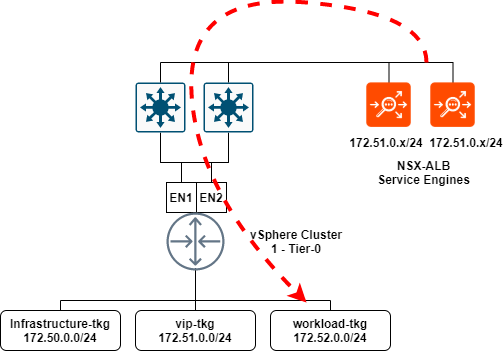
Summary
To summarise the NSX-T and NSX-ALB section: I have created segments in NSX-T which are presented to vCenter and NSX-ALB. These segments will be utilized for the VIP network in NSX-ALB, as well as workload and front-end networks required for TKGS. The below illustration shows the communication from service engines to the NSX-T workload-tkg segment, and eventually the workload clusters that will reside on the segment.
TKGS (Workload Management)
With the fundamental networking now out of the way, we can focus on the deployment and configuration of TKGS or Workload Management.
Before you can deploy TKGS, you need to create a subscribed content library that synchronizes with the endpoint and pulls down the images required for TKGS.
Configure the Content Library
- In vCenter, navigate to Menu -> Content Libraries.
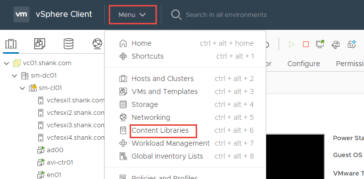
2. Click Create to define a new content library.

3. Enter a Name and Notes (description).
Note: if you have more than one vCenter in linked mode, ensure you have selected the right one.
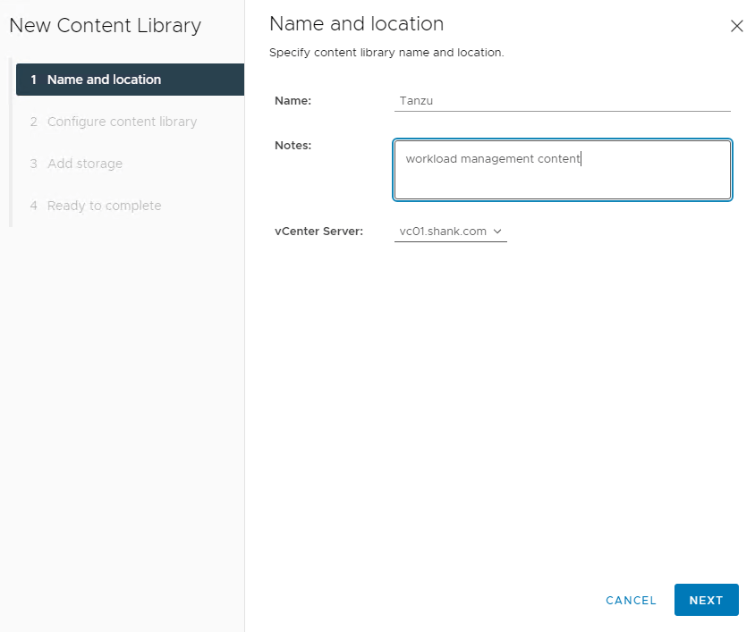
4. Click Next when done.
5. On the next screen, select Subscribed content library and enter the URL, leave Download content set to immediately.
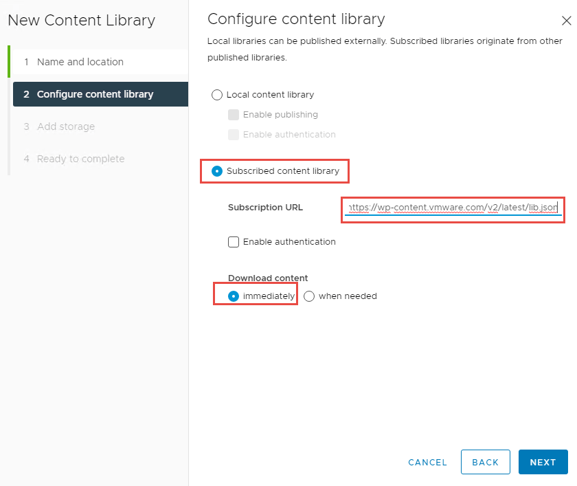
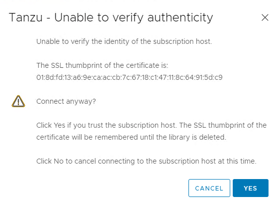
6. Click Next once complete. You will be prompted to accept the certificate, select Yes.
7. Select the storage device you would like the content to be stored on.
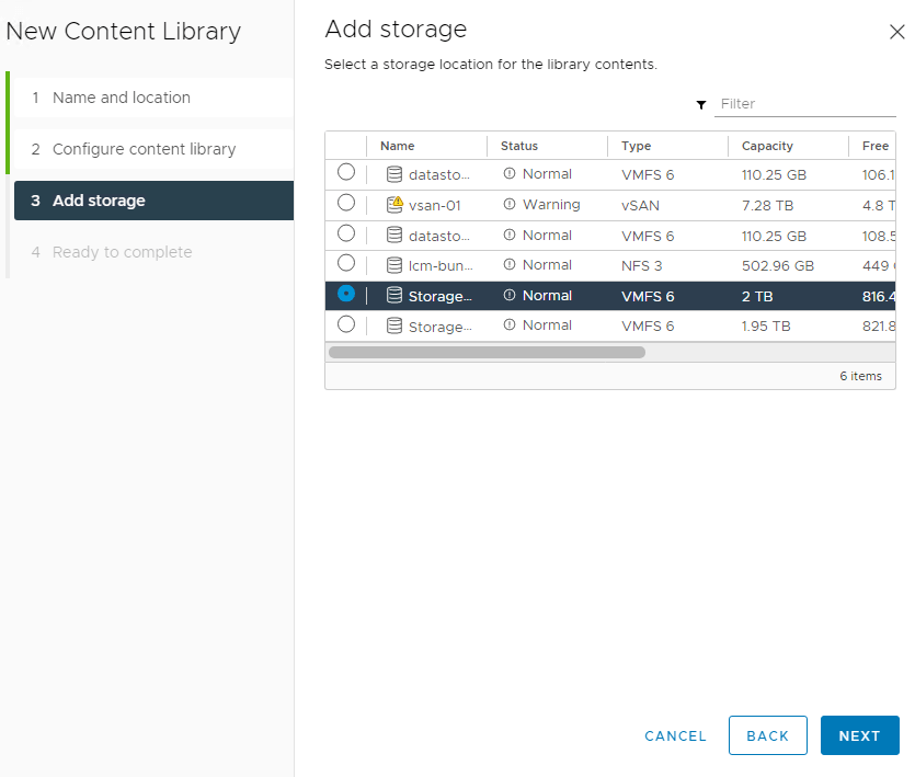
8. Click Next and finish on the final screen. The content library will begin to sync.
Once the Sync Library task completes, your new content library is ready to go.

Deploy the Tanzu Supervisor Control Plane
With all the pre-work now complete, we are ready to configure the Supervisor Control Plane for TKGS.
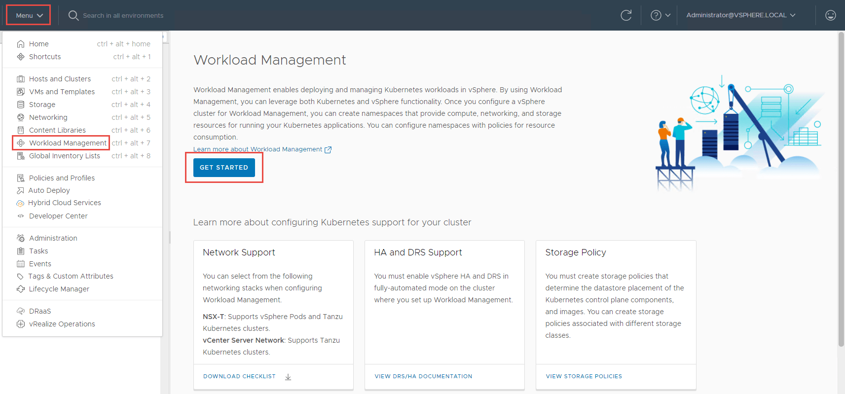
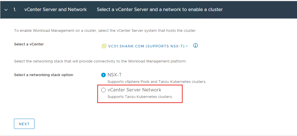
- Navigate to Menu -> Workload Management -> Get Started
2. Select vCentre Server Network and click Next. The reasons for this selection have been explained at the beginning of this article.
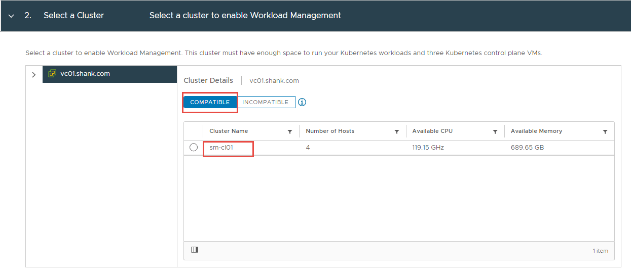
3. Select the Cluster you wish to enable TKGS on and click Next.
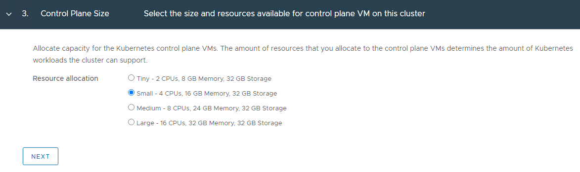
4. Select the size of the Supervisor Control Plane VMs and click Next.
Note: I selected Small for my lab deployment. However, in production you might choose differently.
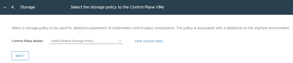
5. Chose the storage policy you want to use in your environment and click Next.
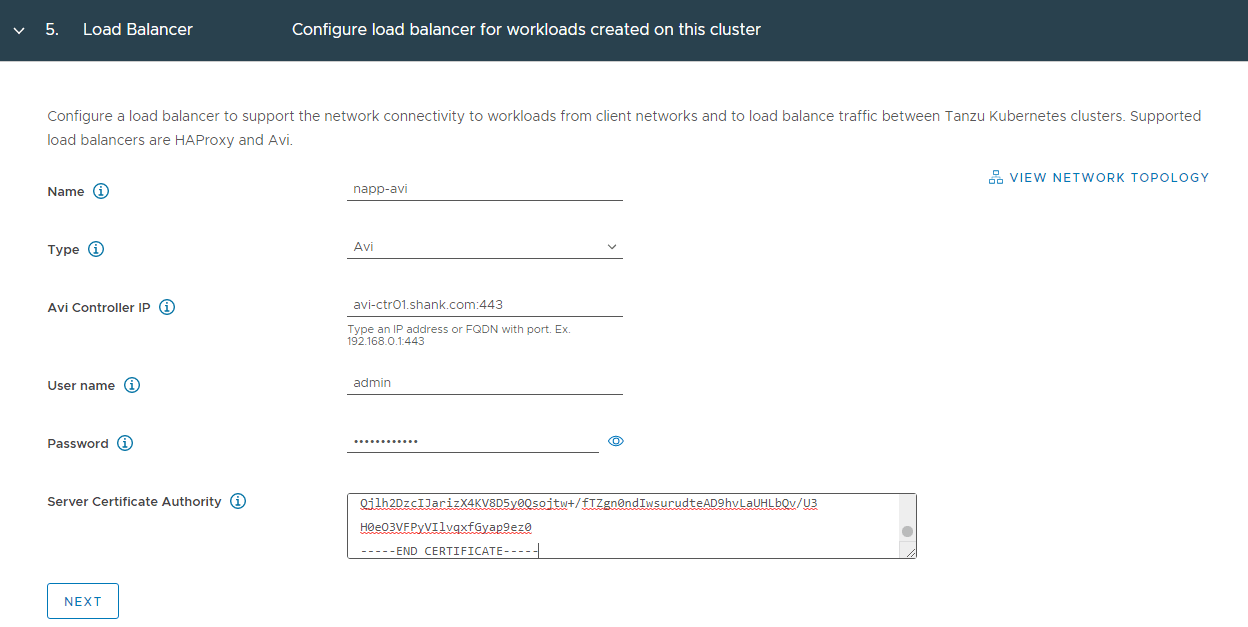
6. Here we define the load balancer configuration. This is where I enter my NSX-ALB details and click Next.
Note: You will also need to use the ‘Controller Certificate’ you saved earlier in this window.
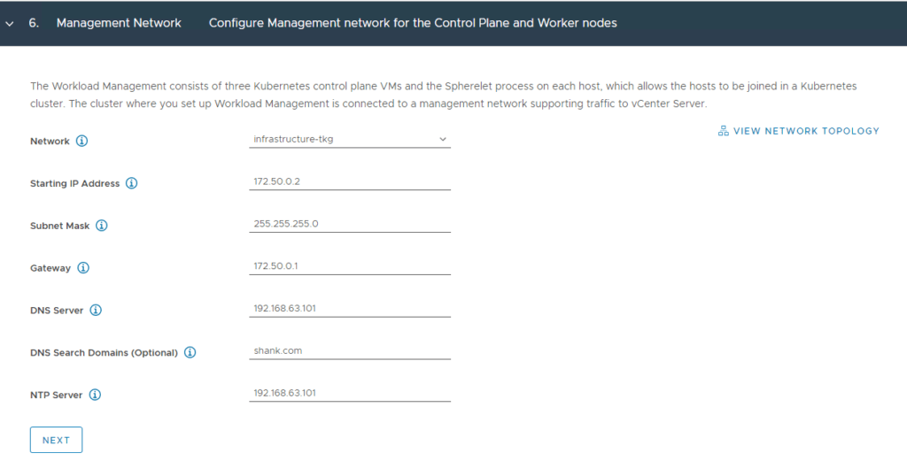
7. Here you define the network that will be used as the management interface for the control plane appliances. In my example, this will be the network labelled “Infrastructure-tkg (172.50.0.0/24)”. Click Next when complete.
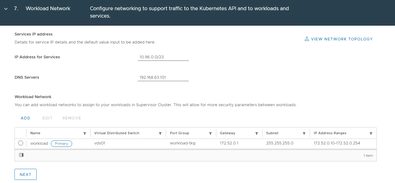
8. There is a subnet prefilled for services, these are non-routable internal networks for the pods. You can choose to define this, however I have chosen to leave it as default.
Note: It is best to ensure there is no overlap of subnets being used in this deployment.
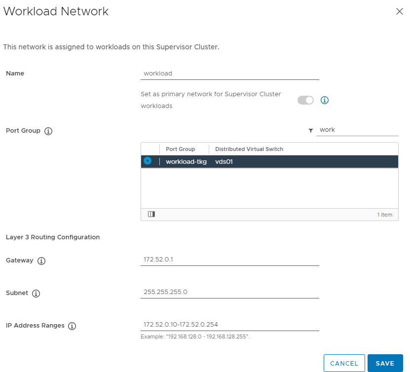
The workload network will be assigned to workload clusters deployed from the supervisor cluster, in my example this will be the “workload-tkg (172.52.0.0/24)” network. Click Save then Next when complete.
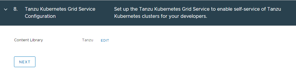
9. This is where you define the Content library that you created earlier and click Next.
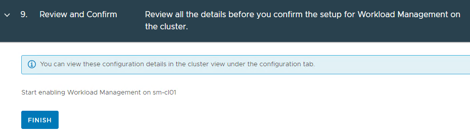
10. This is the final review and confirm section. Click Finish when ready.
Note: This is your last change to change any configuration, if you go past this point and need to change something that can’t be changed later, you will need to disable and re-enable TKGS.
11. The supervisor control plane will now begin to deploy.
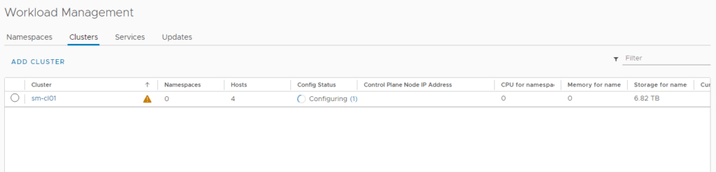
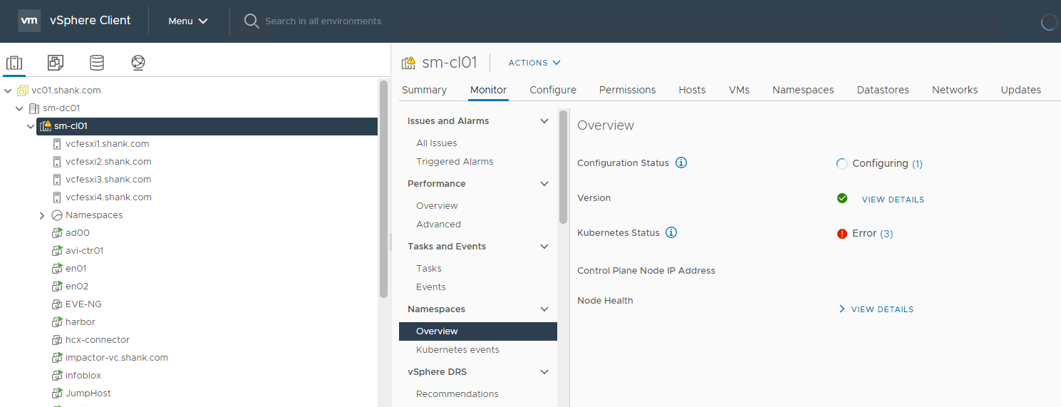
12. You can monitor the deployment in Menu -> Workload Management -> Clusters or Menu -> Hosts and Clusters -> Select the Cluster -> Monitor -> Namespaces -> Overview.
Depending on your environment, the deployment could take between 20 minutes to 1 hour.
Verify Supervisor Control Plane Deployment
Once the deployment is complete, you should see a green tick and running under config status.
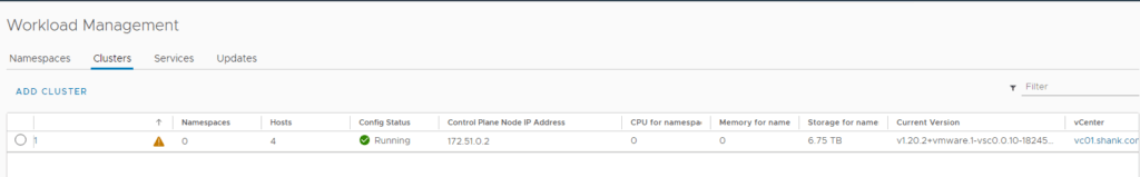
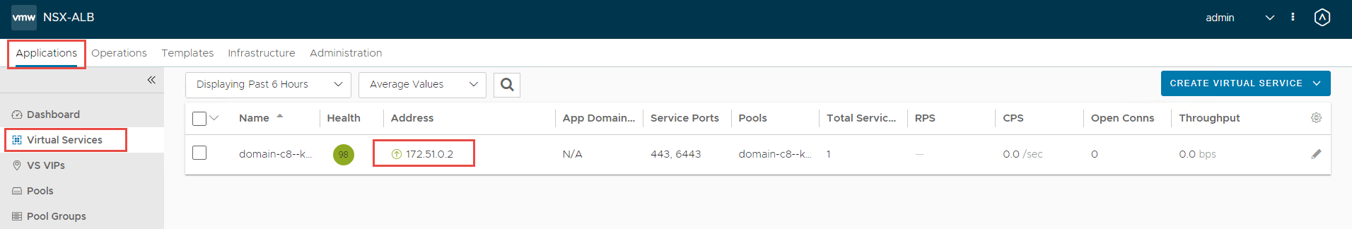
Note the Control Plane Node IP Address (172.51.0.2), this is from the vip-tkg network. You can log back into NSX-ALB, navigate to Applications -> Virtual Services, and you should see the IP assigned to a virtual service.
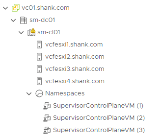
Navigate back to Hosts and Clusters in vCenter, you should to see two NSX-ALB service engines deployed.
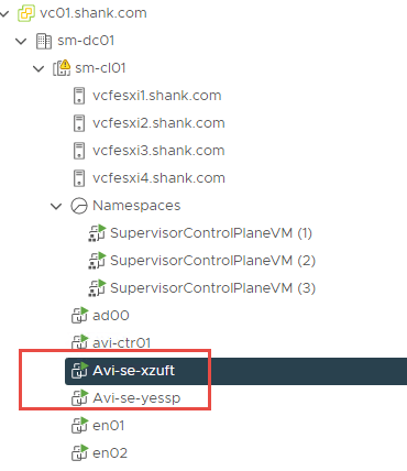
To check the addresses assigned to the supervisor control plane VMs, click on any of them. Then click More next to the IP addresses.
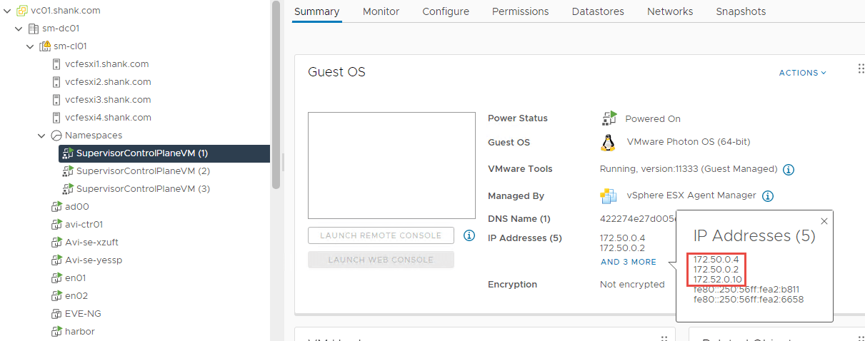
Each of them will have at least one interface and address in the infrastructure-tkg segment and one in the workload-tkg segment. We have now confirmed that all addresses and VIPs have been configured in their respective subnets.
If you use a web browser and navigate to https://172.51.0.2 (the VIP), you will see the front end that can be seen in the image below.
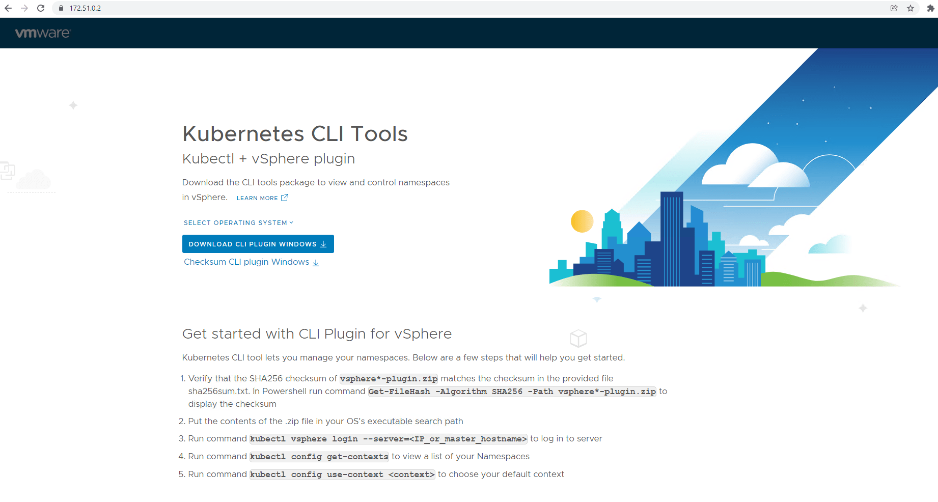
This is also the address / URL that we will now use to connect to the cluster using kubectl and run some further commands.
Using kubectl
Using the jumpbox configured in Part 1, run the below command.
root@jump:~# kubectl vsphere login --server 172.51.0.2 -u [email protected] --insecure-skip-tls-verify

KUBECTL_VSPHERE_PASSWORD environment variable is not set. Please enter the password below
Password:
Logged in successfully.

You have access to the following contexts:
   172.51.0.2
If the context you wish to use is not in this list, you may need to try
logging in again later, or contact your cluster administrator.

To change context, use `kubectl config use-context <workload name>`

#### Changing context to the supervisor context
root@jump:~# kubectl config use-context 172.51.0.2

## Check the namespace
root@jump:~# kubectl get ns
NAME                                        STATUS   AGE
default                                     Active   79m
kube-node-lease                             Active   79m
kube-public                                 Active   79m
kube-system                                 Active   79m
svc-tmc-c8                                  Active   76m
vmware-system-ako                           Active   79m
vmware-system-appplatform-operator-system   Active   79m
vmware-system-capw                          Active   77m
vmware-system-cert-manager                  Active   79m
vmware-system-csi                           Active   77m
vmware-system-kubeimage                     Active   79m
vmware-system-license-operator              Active   76m
vmware-system-logging                       Active   79m
vmware-system-netop                         Active   79m
vmware-system-nsop                          Active   76m
vmware-system-registry                      Active   79m
vmware-system-tkg                           Active   77m
vmware-system-ucs                           Active   79m
vmware-system-vmop                          Active   77m
If you want to check all the pods deployed as part of the supervisor control plane, run the below command. I have not included the output in this article.
root@jump:~# kubectl get pods --all-namespacesThe below command will show the cluster IP’s, as well as the external IP used for access into the system.
root@jump:~# kubectl get svc --all-namespaces
NAMESPACE                                   NAME                                                            TYPE           CLUSTER-IP    EXTERNAL-IP   PORT(S)                        AGE
default                                     kubernetes                                                      ClusterIP      10.96.0.1     <none>        443/TCP                        84m
kube-system                                 docker-registry                                                 ClusterIP      10.96.0.232   <none>        5000/TCP                       84m
kube-system                                 kube-apiserver-lb-svc                                           LoadBalancer   10.96.1.93    172.51.0.2    443:30905/TCP,6443:32471/TCP   77m
kube-system                                 kube-dns                                                        ClusterIP      10.96.0.10    <none>        53/UDP,53/TCP,9153/TCP         84m
vmware-system-appplatform-operator-system   vmware-system-appplatform-operator-controller-manager-service   ClusterIP      None          <none>        <none>                         84m
vmware-system-capw                          capi-controller-manager-metrics-service                         ClusterIP      10.96.1.19    <none>        9844/TCP                       82m
vmware-system-capw                          capi-kubeadm-bootstrap-controller-manager-metrics-service       ClusterIP      10.96.1.178   <none>        9845/TCP                       82m
vmware-system-capw                          capi-kubeadm-bootstrap-webhook-service                          ClusterIP      10.96.1.238   <none>        443/TCP                        82m
vmware-system-capw                          capi-kubeadm-control-plane-controller-manager-metrics-service   ClusterIP      10.96.1.138   <none>        9848/TCP                       82m
vmware-system-capw                          capi-kubeadm-control-plane-webhook-service                      ClusterIP      10.96.0.109   <none>        443/TCP                        82m
vmware-system-capw                          capi-webhook-service                                            ClusterIP      10.96.0.218   <none>        443/TCP                        82m
vmware-system-capw                          capw-controller-manager-metrics-service                         ClusterIP      10.96.1.43    <none>        9846/TCP                       82m
vmware-system-capw                          capw-webhook-service                                            ClusterIP      10.96.0.87    <none>        443/TCP                        82m
vmware-system-cert-manager                  cert-manager                                                    ClusterIP      10.96.1.78    <none>        9402/TCP                       83m
vmware-system-cert-manager                  cert-manager-webhook                                            ClusterIP      10.96.1.199   <none>        443/TCP                        83m
vmware-system-license-operator              vmware-system-license-operator-webhook-service                  ClusterIP      10.96.0.13    <none>        443/TCP                        81m
vmware-system-netop                         vmware-system-netop-controller-manager-metrics-service          ClusterIP      10.96.1.85    <none>        9851/TCP                       84m
vmware-system-nsop                          vmware-system-nsop-webhook-service                              ClusterIP      10.96.1.65    <none>        443/TCP                        81m
vmware-system-tkg                           vmware-system-tkg-controller-manager-metrics-service            ClusterIP      10.96.0.148   <none>        9847/TCP                       81m
vmware-system-tkg                           vmware-system-tkg-webhook-service                               ClusterIP      10.96.1.184   <none>        443/TCP                        81m
vmware-system-vmop                          vmware-system-vmop-controller-manager-metrics-service           ClusterIP      10.96.1.254   <none>        9848/TCP                       81m
vmware-system-vmop                          vmware-system-vmop-webhook-service                              ClusterIP      10.96.0.141   <none>        443/TCP                        81m
Creating and Configure a Namespace
We now need to create a namespace for the worker nodes and control plane to be deployed to. In the next part of this series, NAPP will be deployed onto these worker nodes.
Navigate to Menu -> Workload Management – > Namespaces -> Create Namespace.
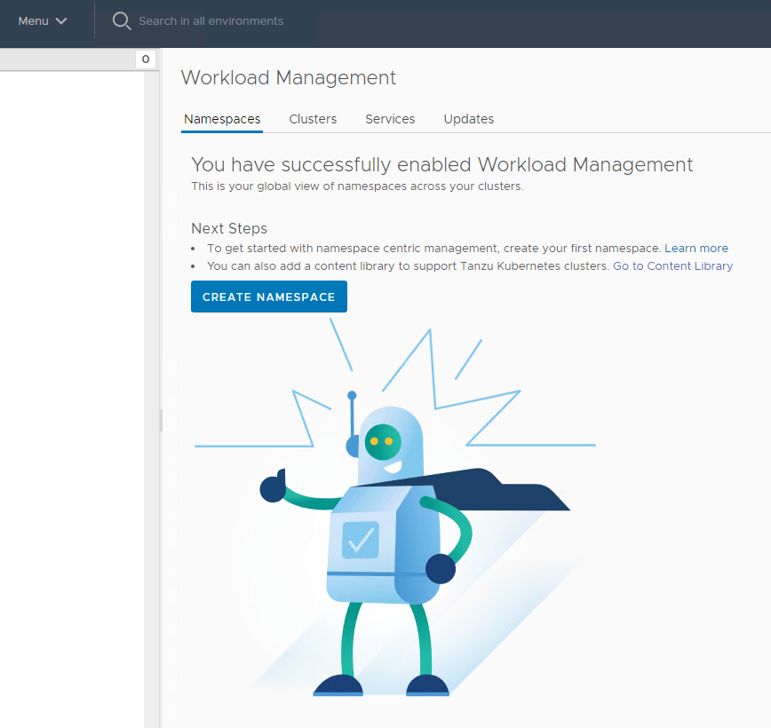
Select the cluster and give it a name.
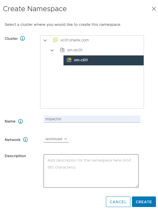
Click Create once you are ready. You should now see the screen below.
We will need to configure permissions, storage policies, VM classes and and a content library.
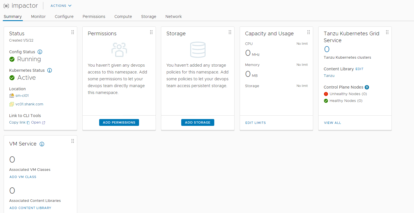
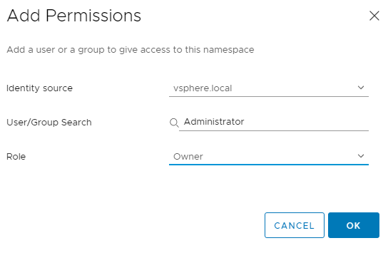
- Click on Add Permissions. In this example, I am going to use the administrator account.
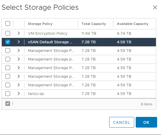
2. Next click Add Storage. I have selected vSAN Default Storage Policy.
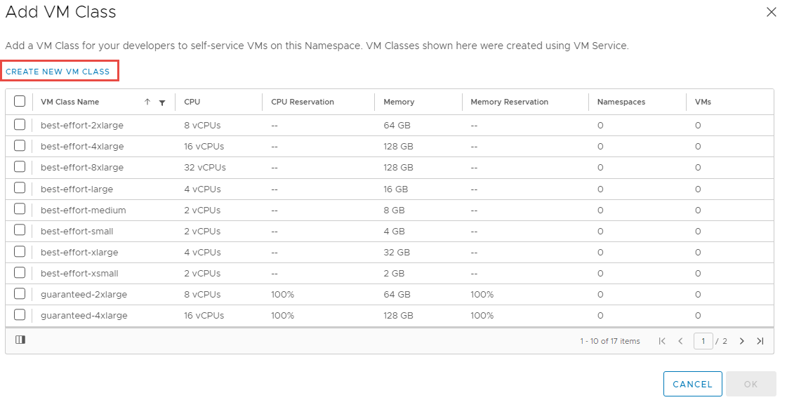
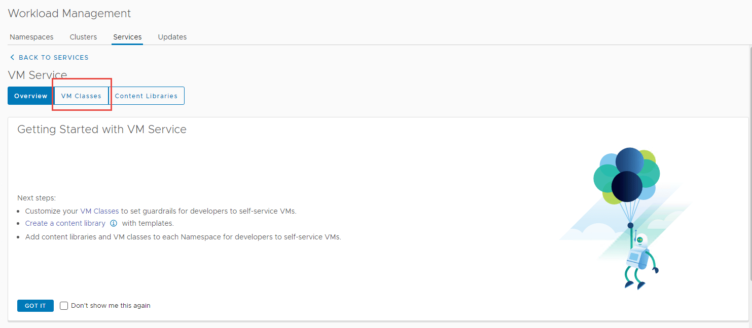
3. Next navigate to Add VM Class. We need to add VM classes, which are pretty much t-shirt sizes for the worker and control nodes to be deployed as.
Depending on which mode of NAPP you want to deploy, you need to configure your VM classes accordingly. A table of the modes and their requirements can be found here. I will be deploying advanced, so will create a VM class to suit.
3.1 Select Create New VM Class.
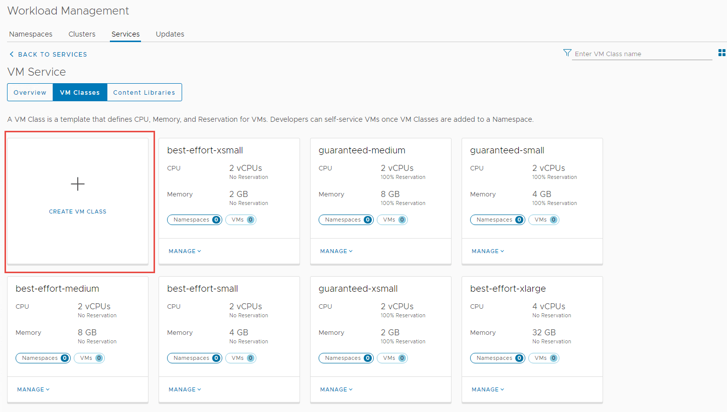
3.2 It will take you to the screen below, select the VM Classes tab.
3.3 Click on Create VM Class.
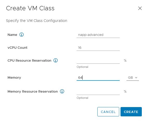
3.4 Fill in the required specifications and then click Create.
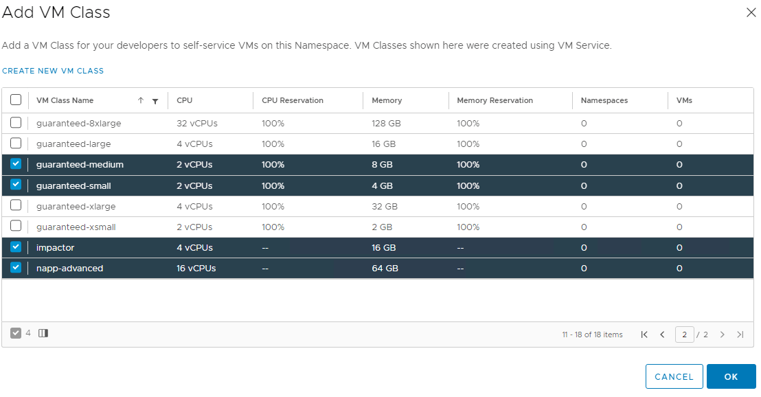
3.5 Navigate back to the summary page on the name space and click on Add VM Class again.
You should now be able to see the VM Class you just created, I have selected the one I just created, as well as some others. Click Ok when you are done.
4. Navigate to Add Content Library and select the content library you created earlier.
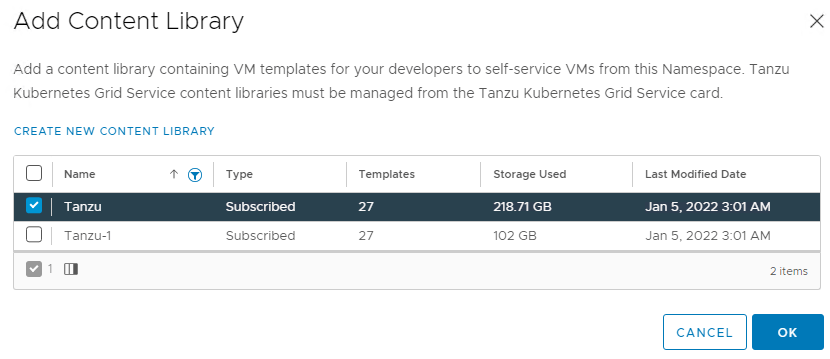
Deploy the Worker Control Plane and Nodes
We are now ready to deploy the worker nodes. You will need to use kubectl on the jumpbox once again.
To build out this cluster I will use the commands below. I have provided a copy of my cluster.yml file here.
Note: depending on which NAPP form factor you are deploying, your resource requirements may vary, each form factors requirements are here. My cluster yaml has been created for the advanced deployment, which includes NSX Intelligence.
root@jump:/mnt/tanzuFiles# kubectl vsphere login --server 172.51.0.2 -u [email protected] --insecure-skip-tls-verify

KUBECTL_VSPHERE_PASSWORD environment variable is not set. Please enter the password below
Password:
Logged in successfully.

## deploy the cluster
root@jump:/mnt/tanzuFiles# kubectl apply -f cluster.yml

## workflow kicked off
tanzukubernetescluster.run.tanzu.vmware.com/impactorlab created
You will then start to see the VM’s being created in vCenter.
Allow the process to complete. You can run the command below to check on the status of the deployment. Think of it as a log tail, which displays events as they occur during the creation.
root@jump:/mnt/tanzuFiles# kubectl get events -n impactor -wVerifying the Impactor Namespace Deployment
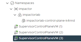
The command below shows the Impactor nodes have been deployed and powered on.
root@jump:/mnt/tanzuFiles# kubectl get virtualmachine -n impactor
NAME POWERSTATE AGE
impactorlab-control-plane-k4nnd poweredOn 12m
impactorlab-workers-5srcx-7c776c7b4f-bts8m poweredOn 8m29s
impactorlab-workers-5srcx-7c776c7b4f-kjr6j poweredOn 8m27s
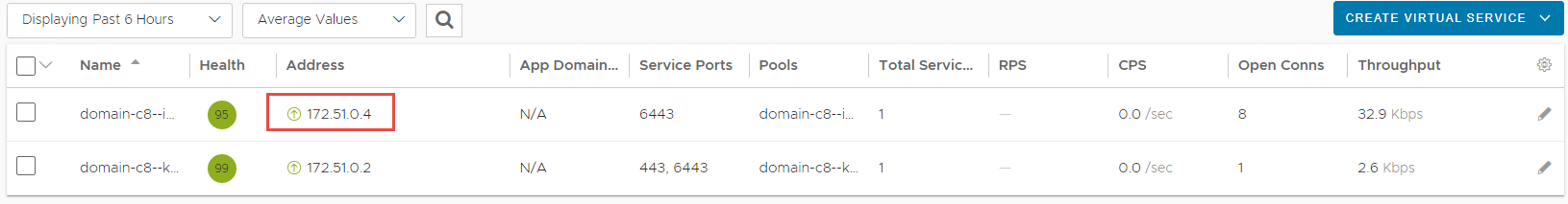
impactorlab-workers-5srcx-7c776c7b4f-v98z8 poweredOn 8m28sThe command below shows an ingress or external IP assigned to the cluster.
root@jump:/mnt/tanzuFiles# kubectl get svc -n impactor
NAME                                TYPE           CLUSTER-IP   EXTERNAL-IP   PORT(S)          AGE
impactorlab-control-plane-service   LoadBalancer   10.96.0.12   172.51.0.4    6443:31049/TCP   13m
The Virtual Service has been configured in NSX-ALB.
The cluster is deployed in vCenter.
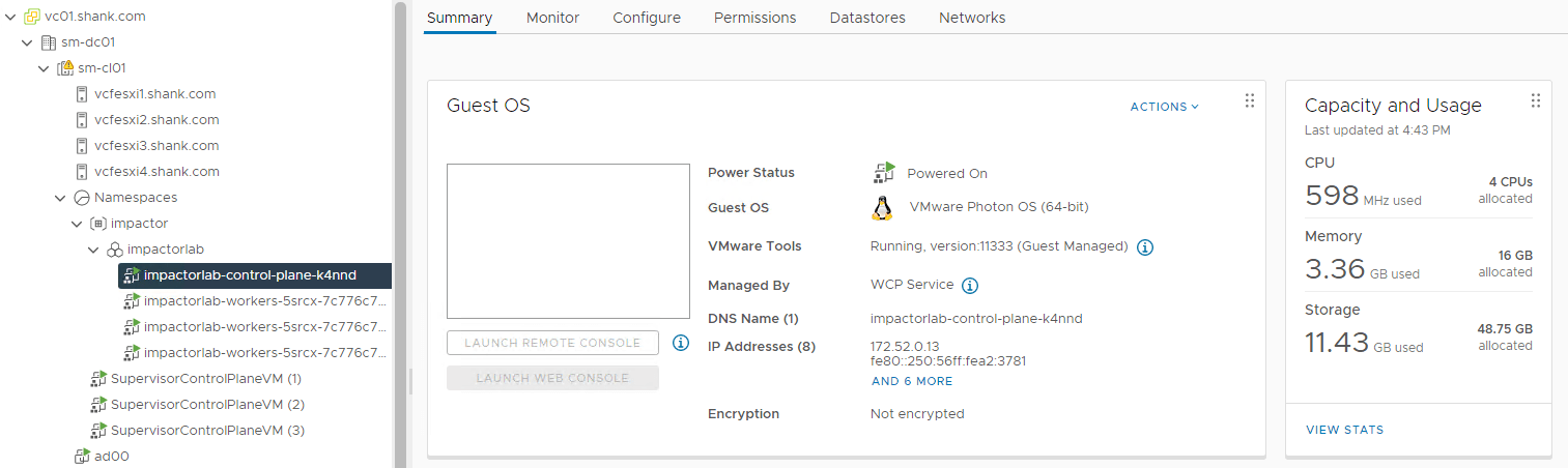
The nodes have been assigned with an IP address in the workload-tkg range.
Next Steps
NSX Application Platform Part 4: Deploying the Application Platform
The final part of the series demonstrates the deployment process for NSX Application Platform and its security features (NSX Intelligence, Network Detection and Response, and Malware Prevention.
Thanks for your share~
Those are very good news for napp deploy
we are wait for Part 4!!!
No problems, part 4 should be done very soon.
That’s awesome!
I’m looking forward to seeing it.
please describe deploying intelligence 3.2 via the harbor.
Hi Reza,
Intelligence will be deployed with NAPP which will be described in part 4 :).
Thanks for the feedback!
The Setting process for Tanzu, it is clear.
thank you
Excellent, i’m glad. Thanks for letting me know!