
Deterministic VMware NSX Edge Failure Conditions
Why is knowing the different VMware NSX Edge Failure Scenarios Important?
As more data centres adopt VMware NSX and embrace it’s powerful overlay routing functionality, very few take the time to truly understand the datapath and the different VMware NSX Edge Failure Scenarios.
This article will equip readers with the ability to predetermine what a north-south failure would look like, understanding this behavior is useful when performing failover testing or in real-world failure scenarios.
I cover the data plane, tunnel endpoints (TEPs), logical routing, and routing with the physical fabric in-depth, in my book “NSX-T Logical Routing“, if you would like to master the VMware NSX data plane.
This article will be broken down into two main sections:
- Supported VMware NSX Edge Failure Tests
- Unsupported VMware NSX Edge Failure Tests
- Why is knowing the different VMware NSX Edge Failure Scenarios Important?
- Supported VMware NSX Edge Failure Tests
- Unsupported VMware NSX Edge Failure Testing
- Summary
Supported VMware NSX Edge Failure Tests
- Tier-0 Service Router (SR) Routing Down
- Edge node events
- TEPs, RTEPs, BFD Sessions
- Proccess failures
- Service Router Ranking / Scoring and Preemption
- Maintenance Mode
Note: the scenarios demonstrated in this article have been tested on version 3.2.1.2 and 4.0.1.1. If there are any behavioral changes, they will be specifically called out.
Tier-0 Service Router (SR) Routing Down
This scenario is likely to be one of the most common, simply put, it occurs when an Edge node hosting a Tier-0 SR loses its upstream routing peers. This includes BGP adjacencies, OSPF neighbors, static neighbours with BFD, or any other configured BFD sessions with the physical fabric.
Without diving too deep into how the data plane works in VMware NSX (refer to the link in the introduction), the Edge nodes host the SR’s, for both the Tier-1 and Tier-0 gateways.
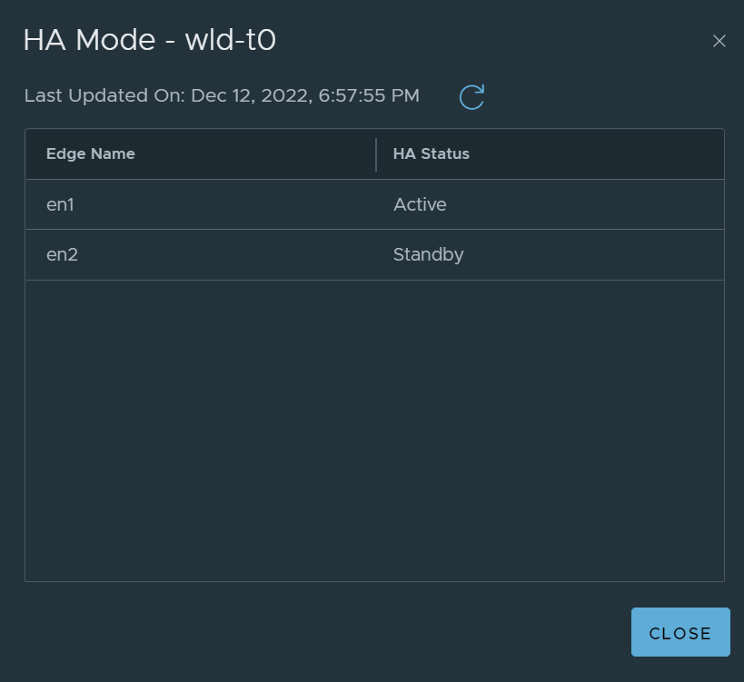
In this scenario, we are specifically referring to the Tier-0 SR, which depending on the HA mode of the Tier-0 gateway (either Active-Active or Active-Standby), either one or all Edge nodes in the attached Edge cluster will host an active Tier-0 SR.
In this example, I will demonstrate a Tier-0 gateway configured in Active-Active, as it is generally the most common approach. Refer to the diagram and image below.
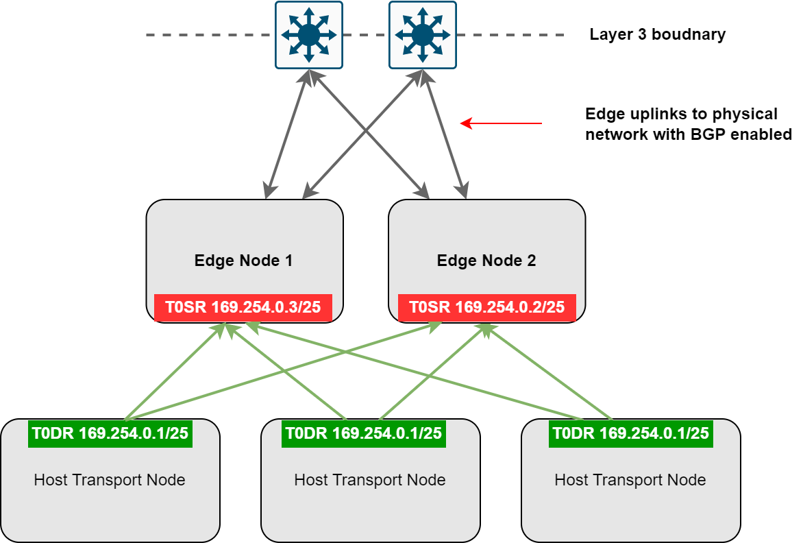
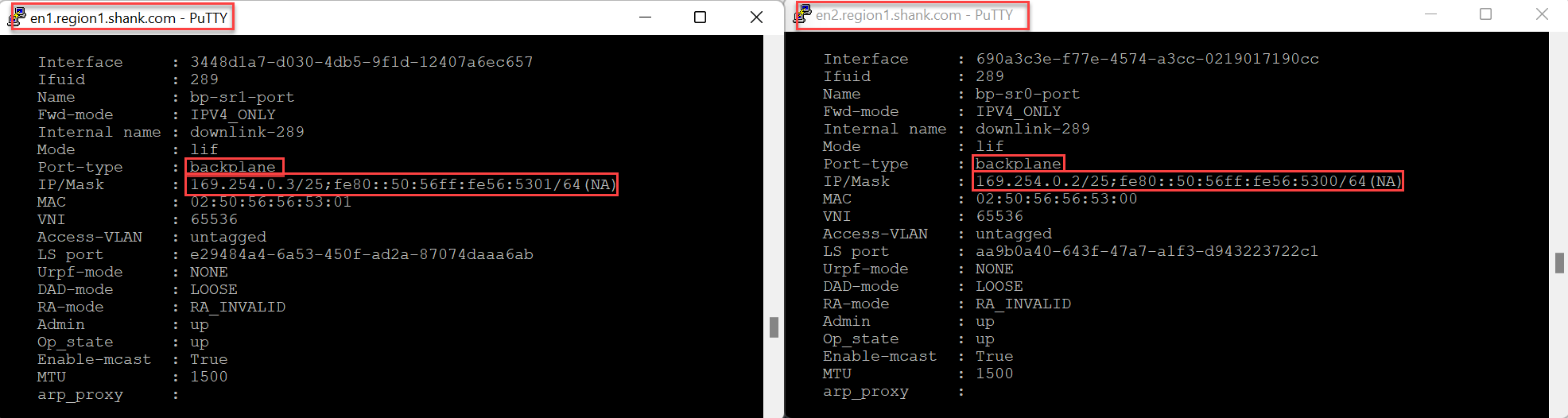
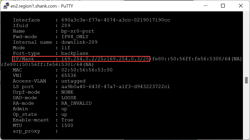
Each Edge Node will have a logical interface configured on the Tier-0 SR in the 169.254.0.0/24 range, this indicates that it is a routing backplane port, which is what the Tier-0 Distributed Router (DR) connects and installs a default route to.
As mentioned earlier, this article will not dissect VMware NSX overlay routing operations.
The following image shows EN1 and EN2, both with their respective backplane interfaces.
Routing Failed to Edge Node 1
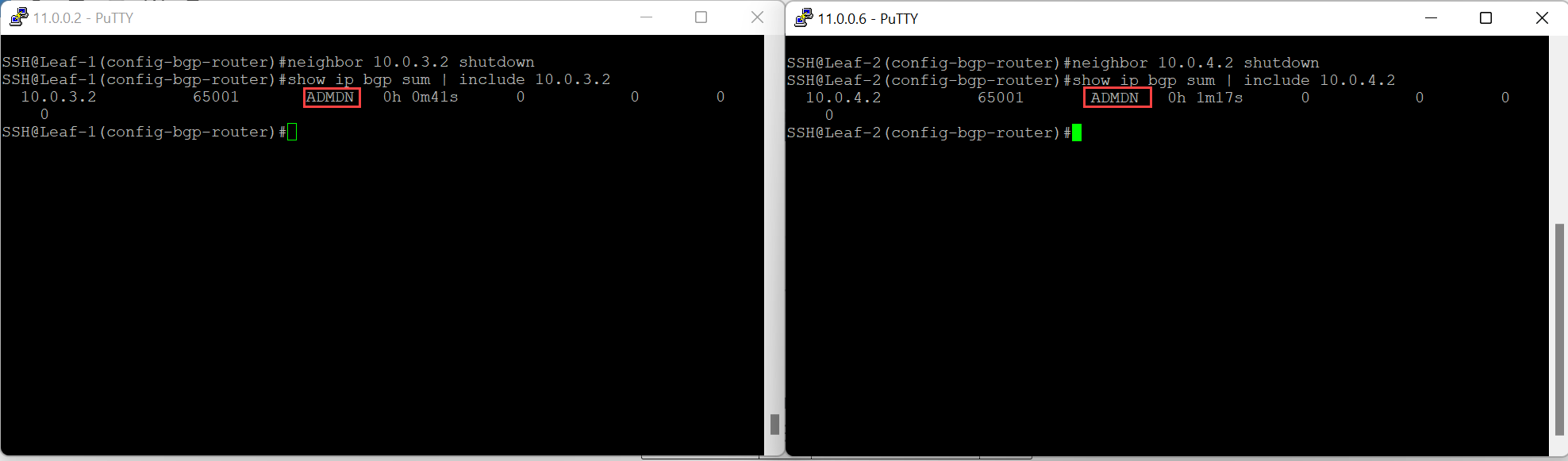
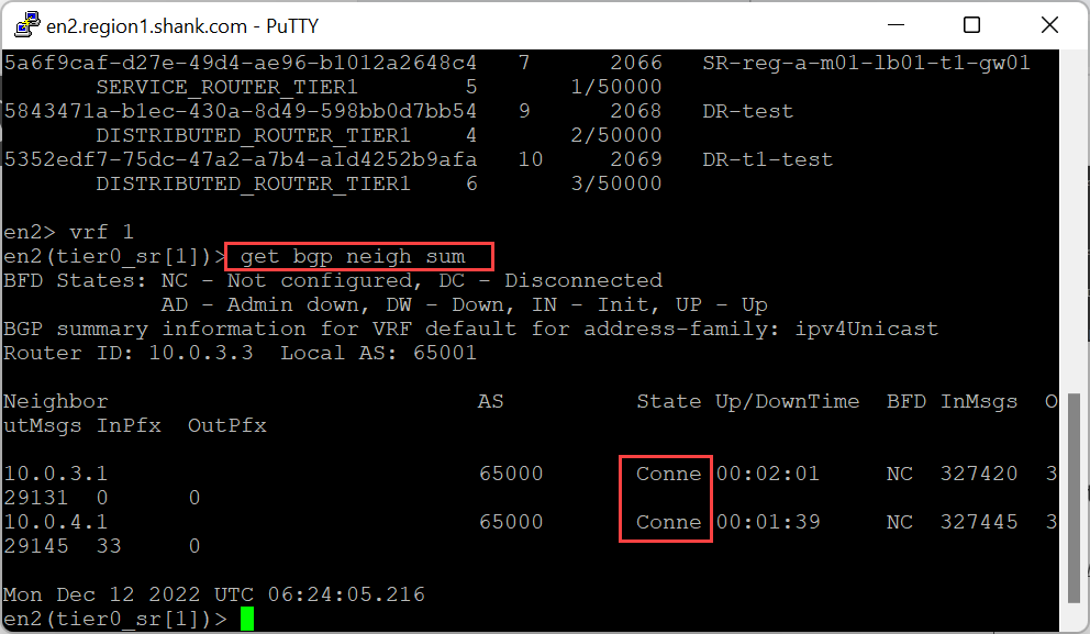
Triggering a routing down event in this scenario involves shutting down the BGP adjacency on the two top of rack switches to Edge Node 1, this is just the way I simulated this and is not the ONLY way a routing down event could occur. Let’s quickly check the status of the Edge Node before the peering’s are shutdown.

As you can see, both Edge nodes are healthy with 14 active tunnels each.
Now, shutdown the BGP neighbour on the upstream switches.
Even though the upstream routing peers are down, the Edge nodes remain in an “up” state with tunnels still instantiated. This is because only the routing peers are down, therefore, the TEP interfaces on all transport node can still communicate with each other.

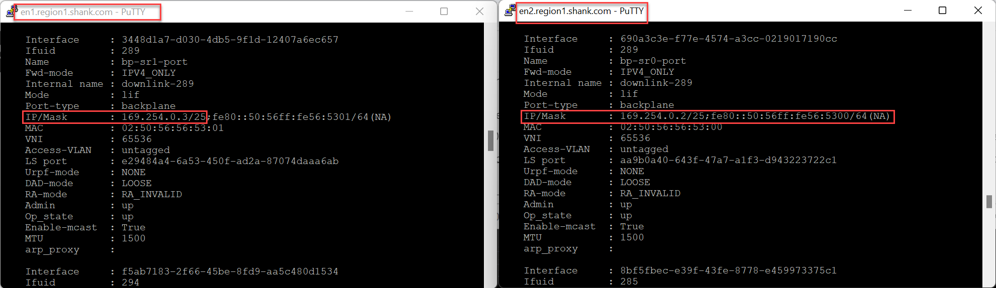
In the image below, you can see that the address 169.254.0.3/25 has moved from Edge Node 1 to Edge Node 2.
The backplane port moves to the remaining Edge node as this is less resource intensive than removing the next hop from all down stream peers forwarding tables.
Whilst the routing peers are down to Edge Node 1, all packets that would have been sent to 169.254.0.3/25 on Edge Node 1, will now be sent to Edge Node 2. Once the BGP peers (even if just one was brought back up) are re-instated, the backplane port will immediately move back to Edge Node 1, as can be seen in the images below.
Re-enable a single upstream peer to Edge Node 1.
The backplane port moved back to Edge Node 1.
This concludes the Edge up, routing down scenario.
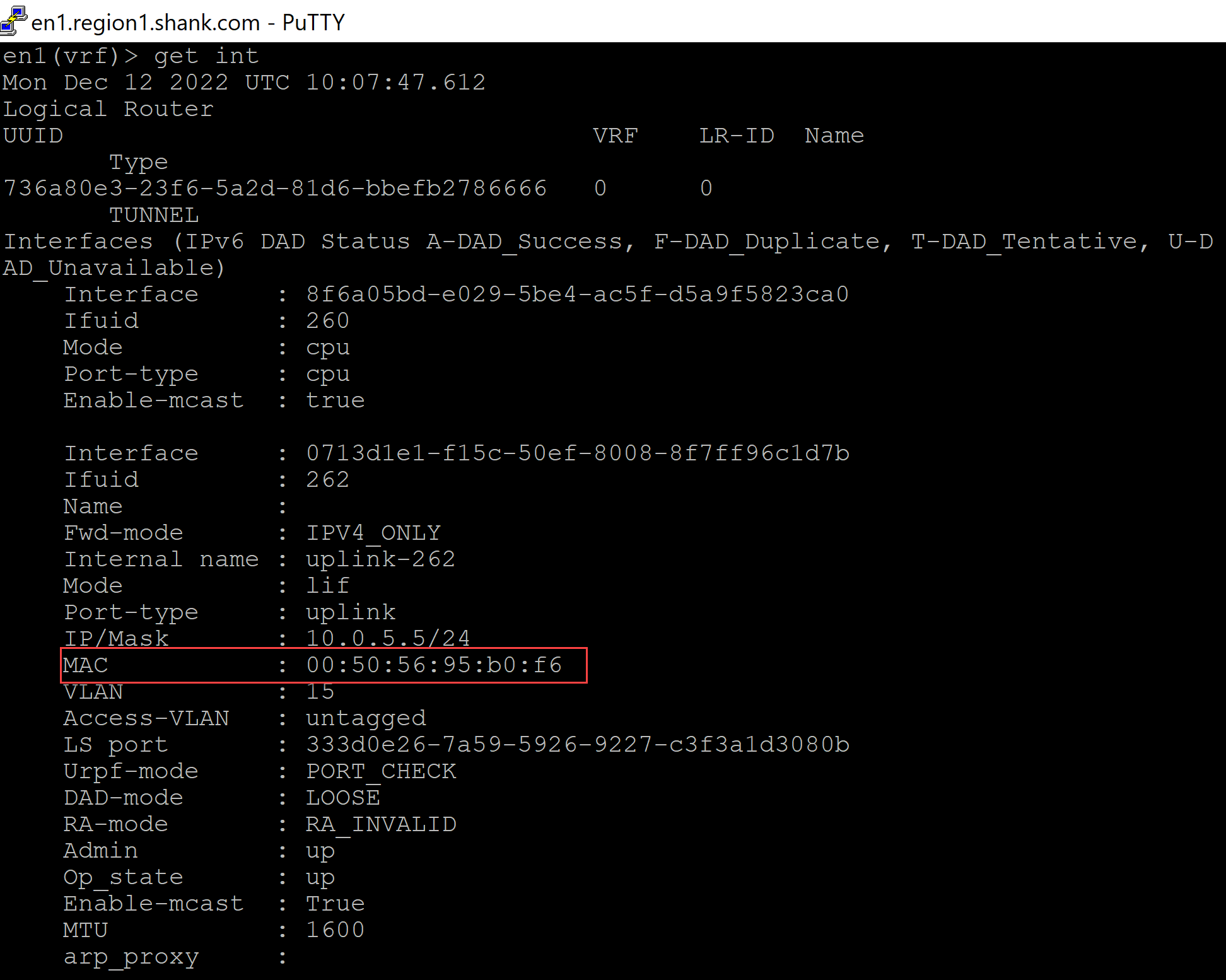
Tunnel Endpoint (TEP) Interfaces Unreachable
For an Edge node to be operationally healthy, it must have at least one TEP interface active, that is, sending and receiving tunneled traffic. Each TEP tunnel has an associated BFD session, which assists in determining whether a tunnel is operational or not.
By default, an Edge node has BFD sessions from each of its interfaces (TEPs and Management). The image below shows BFD sessions from the TEP and management interfaces of Edge Node 1.
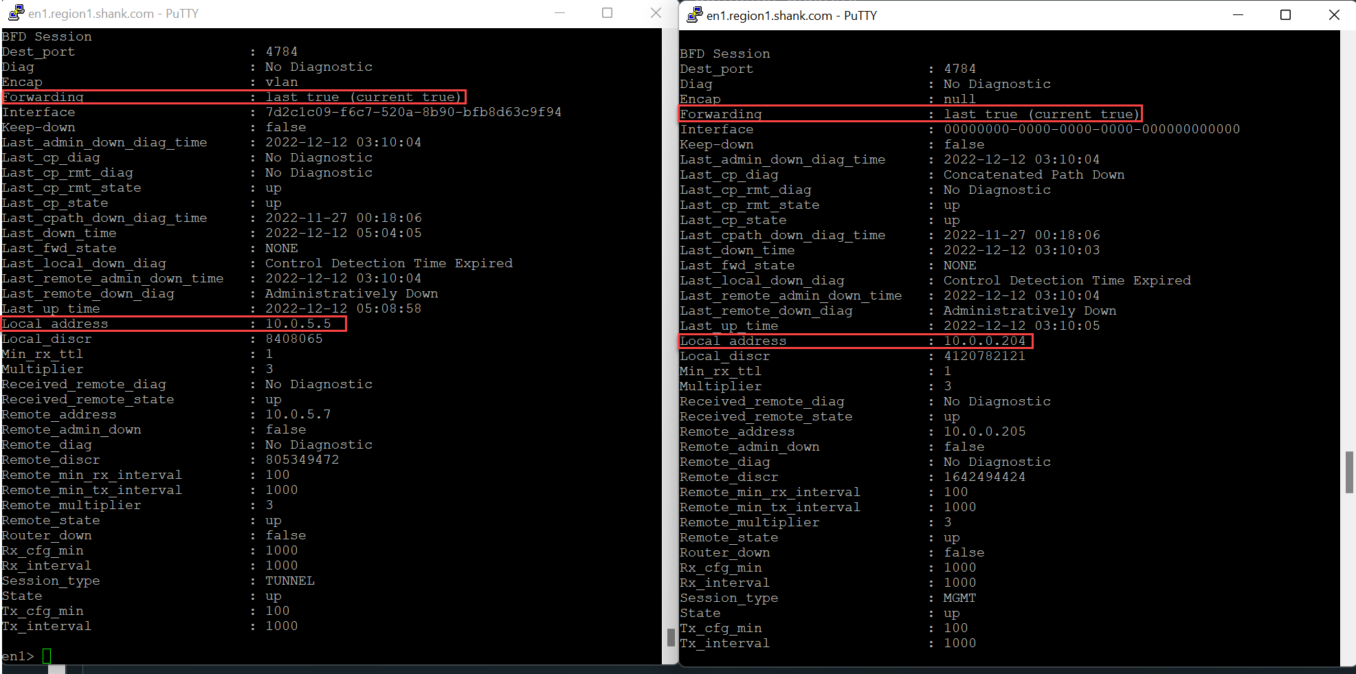
The example above shows a BFD session from Edge Node 1’s TEP interface with address 10.0.5.5 and its management interface 10.0.0.204.
Tunnel Endpoint (TEP) Connectivity Failure
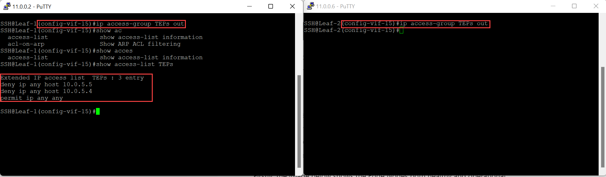
Once again, there are many ways to simulate this issue, in the real world, this could be the result of a firewall filtering packets or even some form of routing issue. In this example, an outbound access control list (ACL) on the switched virtual interface (SVI) on both switches, will be applied. This will filter packets destined to both TEP interfaces on Edge Node 1.
Firstly, the image below shows the Edge Nodes both healthy and operational.

The image below shows configured of the ACL, and it being applied to the SVI on both switches.
The result is immediate, the UI shows the Edge Node as down, even though the management interfaces is still operational.

The image below shows the output of the same interfaces and their BFD sessions shown earlier.
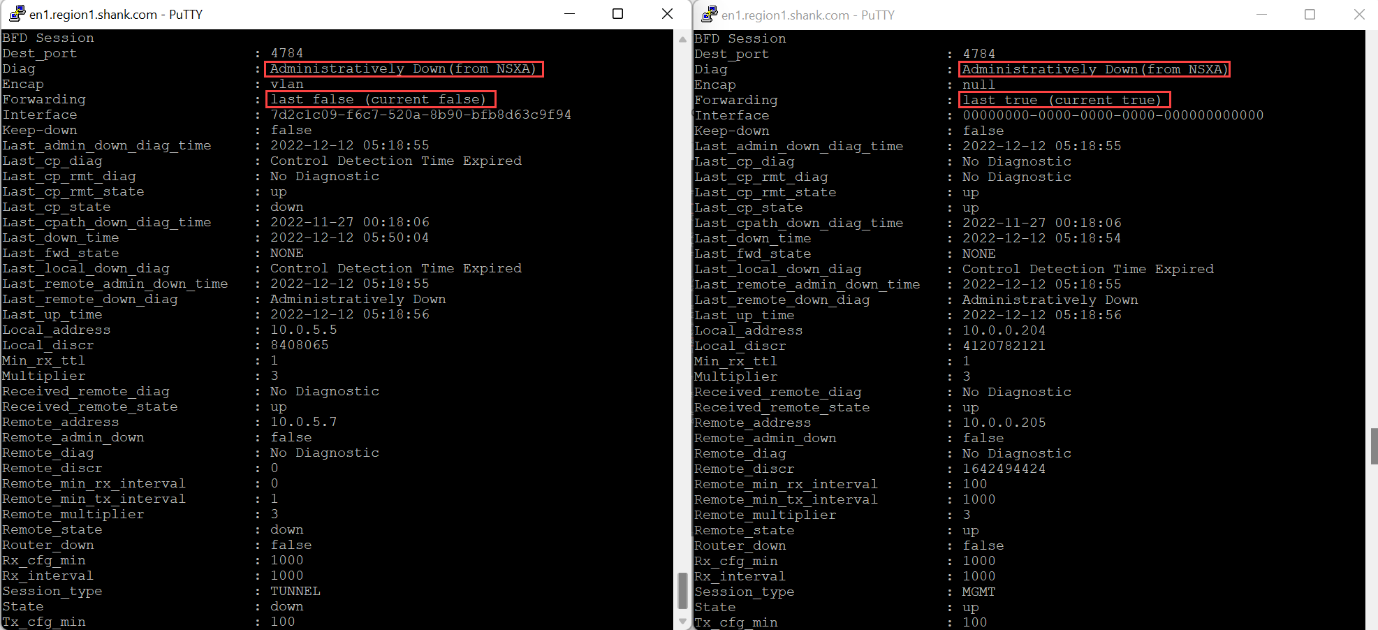
The Edge will be placed into an administrative shutdown which results in a Data Plane outage even when the Management Interface BFD session is up.
This would be due to all TEP Interfaces being down which is correlated by the BFD message “Control Detection Time Expired”.
“Control Detection Time Expired” messages results from replies to BFD hello messages sent from the TEP Interface not being received within the specified time interval.”.
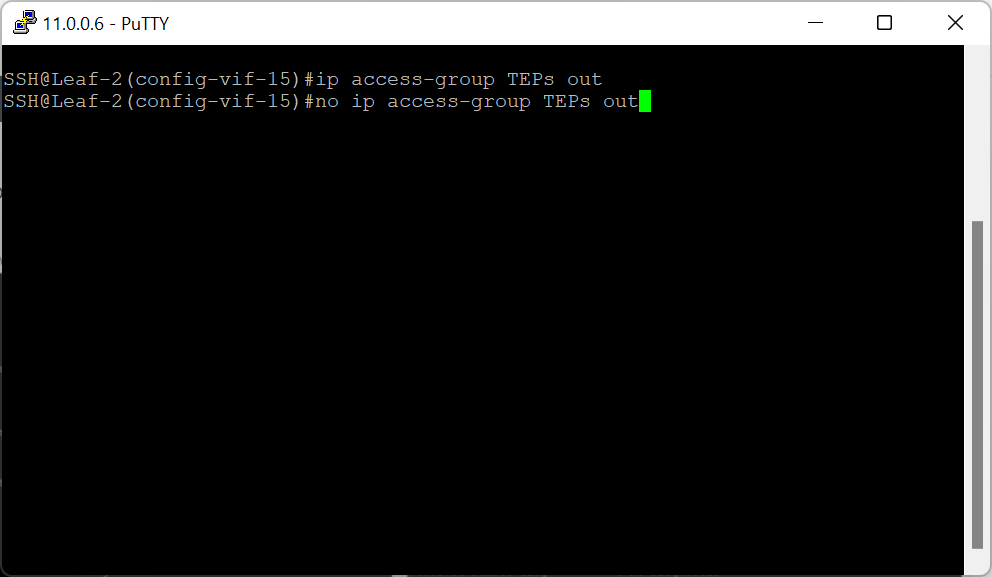
To further test this, removing the ACL from the second switch allows TEP connectivity back into the Edge Node and re-instate GENVE / TEP tunnels.
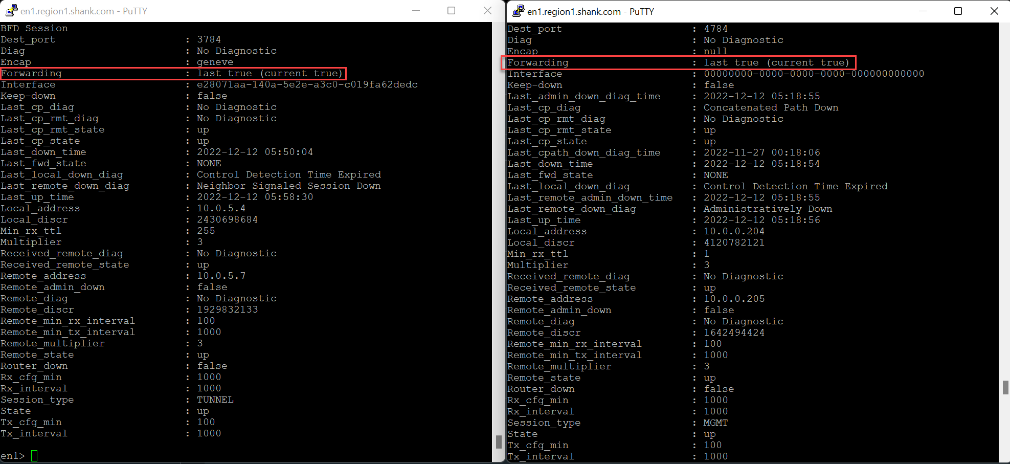
As you can see, Edge Node 1 is active again, with connectivity re-instated to a single TEP interface.

You will still have tunnels down to the Edge Node, and that is expected as both interfaces have not been re-instated.
Comparing the output on VMware NSX 4.0.1.1
The result on the latest version of NSX is the same, however, the message is slightly different, as you can see in the image below.
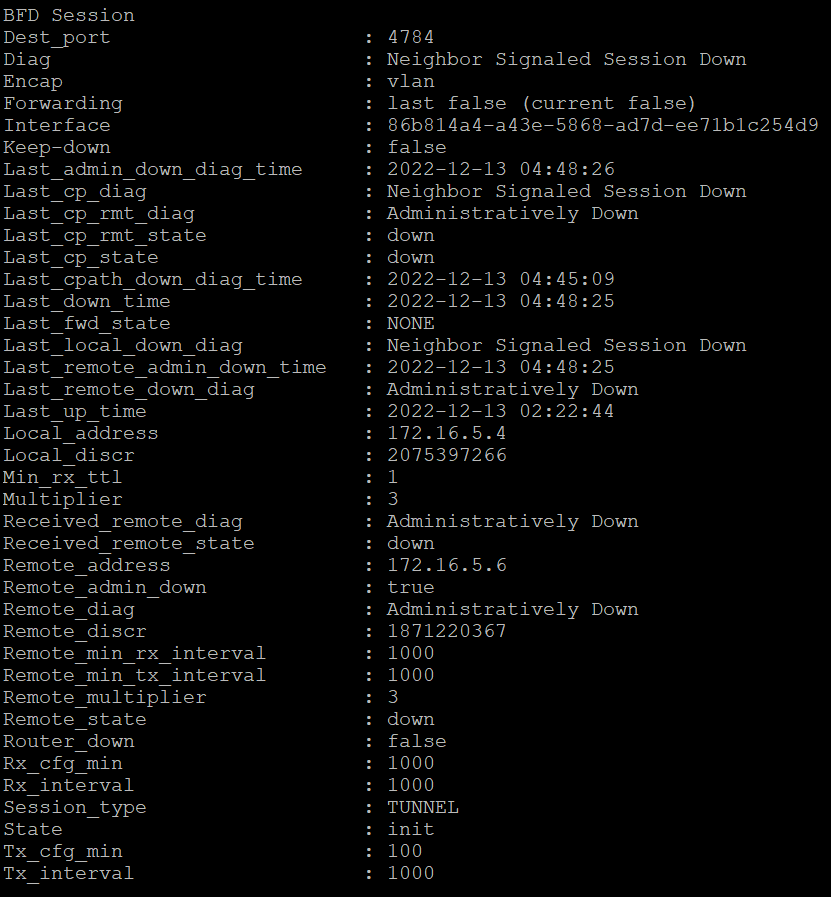
The change is in the diagnostic message, instead of “Control Detection Time Expired”, it is now “Neighbor Signaled Session Down“. That is the only difference between the two versions.
This section detailed the expected behaviour with TEP interfaces, you can expect to see the same results if you had an environment with NSX Federation and RTEPs.
Process Failures
There is no easy way to test process failures on an Edge nodes to understand their impact on Edge functionality. Amongst the numerous processes that run on the Edge nodes, several of them when down will impact normal Edge behavior.
Whilst it is hard to test these processes, you would typically see them arise in one or more of the following situations:
- Process crashes (FRR etc) which could be due to resource or operating system issues
- Memory exhaustion on the appliances
- Non-responsive edge nodes or timeouts
Service Router Ranking / Scoring and Preemption
A gateway that has an Edge cluster attached and/or stateful service(s) configured is typically configured in Active-Standby HA mode. This effectively means, one of the Edge nodes in the attached Edge cluster will be actively forwarding packets, while the other one is in standby.
This article will focus on typical Active-Standby in VMware NSX, I will post a second article diving deep into the behaviour with Active-Active stateful services on a gateway.
When an Edge node is either elected or selected as the active node for the gateway, a scoring or ranking system is put in place. The lower the score the higher the priority. Note, this system is only relevant when preemption is enabled on the gateway.
- Rank 0 = Higher priority
- Rank 1 = Lower priority
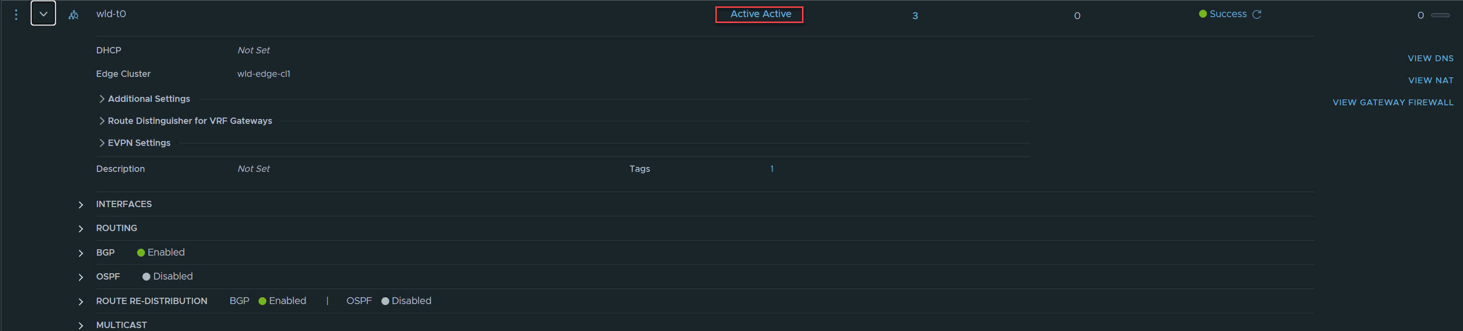
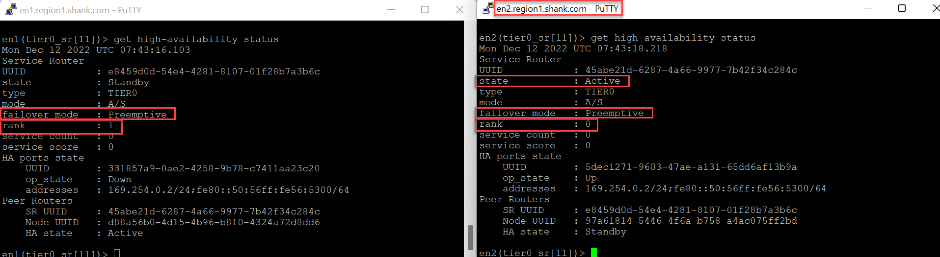
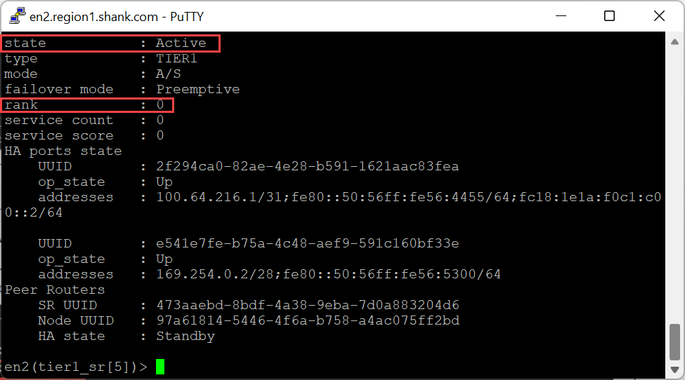
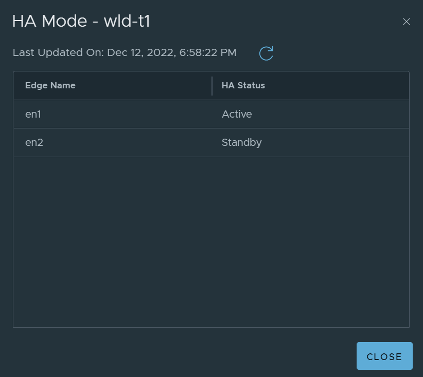
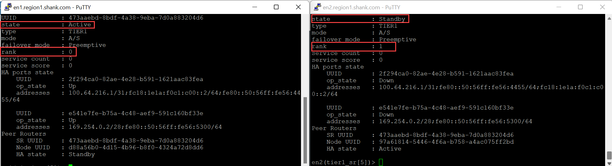
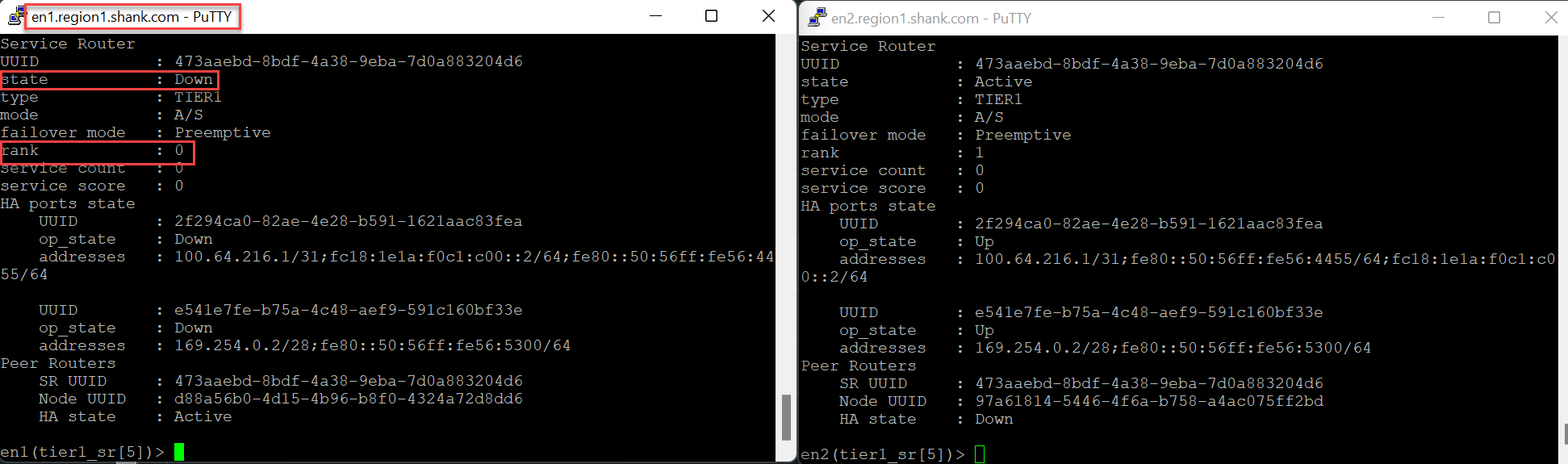
In this scenario, Edge Node 2 is active for the gateway wld-t1.
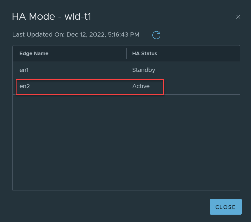
You can use the CLI to verify the score/rank, this can be done by navigating to the wld-t1 SR’s vrf and issuing the command “get high-availability status”.
Determining the impact of Routing Down on an active Service Router (SR)
This section will repeat both of the routing down and TEP connectivity tests to verify the impact on the rank of each Edge node.
First I will start with shutting routing down to Edge Node 2, which is currently active for WLD-T1 SR, which once again has the stateful service.
Confirming Edge Node 2’s routing peers are offline and it has no more BGP adjacencies.
The image above confirms that Edge Node 2 no longer has any established BGP adjacencies.
Now we recheck the WLD-T1-SR score/rank.
Notice, Edge Node 2 is still active for the SR. Earlier when we tested the routing down event, remember, the Edge node did not move to an offline state. This was because the TEP interfaces were still active.
That is the reason the Edge node is still active in this case. The traffic will still be forwarded from the Tier-1 SR to the Tier-0 DR on Edge Node 2, which will forward it to the Tier-0 SR, and finally make a forwarding decision.
In this case, the Tier-0 gateway is configured in Active-Active with inter-SR routing enabled. This article will not cover the operations of inter-SR routing, but it’s primary use-case is to prevent blackholing traffic in the event of losing an upstream routing peer. Edge Node 2 will will receive the packet on its Tier-0 SR interface, the forwarding table will be checked, then using inter-sr routing, the packet will be forwarded to Edge Node 1 and then finally out to the destination. The forwarding table on Edge Node 2’s Tier-0 SR will be updated to forward all packets destined outside of the NSX domain to Edge Node 1. If the destination is internal to NSX and within the routing domain, the prefix lookup and forwarding process will occur on Edge Node 2.
What happens if the Tier-0 gateway is also in Active-Standby or the stateful service is configured on the Tier-0 gateway?
In the same situation, if the SR was shifted to the Tier-0 gateway, a routing down event on the Edge Node would move the active SR onto the remaining Edge node. The image below shows the Tier-0 gateway after the upstream peers were shutdown.
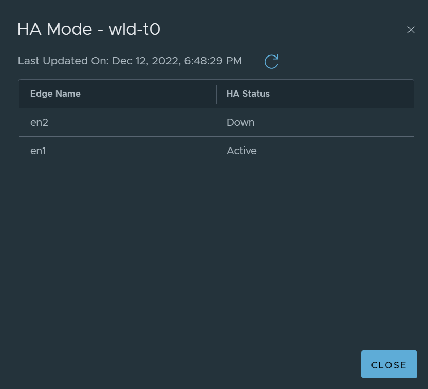
This image shows the SR for the Tier-1 gateway is still active on Edge Node 2.
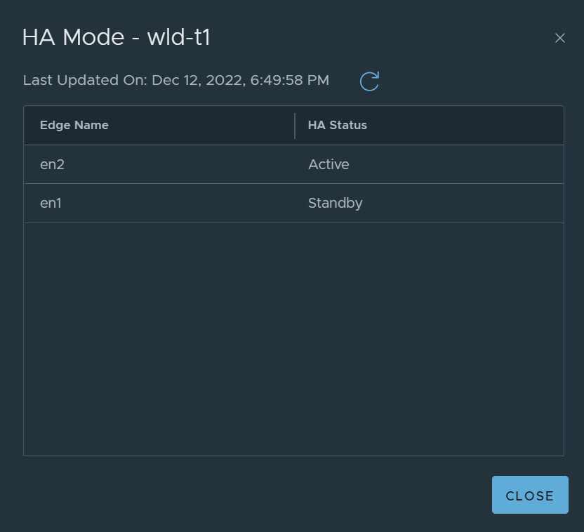
Remember, a routing down event will directly impact the Tier-0 SR, however, the Tier-1 SR can still be active on Edge node 2. The Tier-1 SR has a default route to the Tier-0 DR, if the destination prefix resides within NSX, the Tier-0 DR should be aware of the prefix (depending on the logical NSX architecture), and a forwarding decision can be made on Edge Node 2.
Determining the impact of TEP Interface Connectivity Issues on Service Router (SR) Placement
In this section, we will retest the TEP connectivity scenario in conjunction with the Tier-1 and Tier-0 Service Routers, with preemption configured, this tests the ranking system in conjunction with TEP connectivity failure.
The Tier-1 SR and Tier-0 SR are active on Edge Node 1.
The rank is lower on Edge Node 1, and you can see it is active in the CLI view below.
I won’t cover the ACL’s again, but from this point onwards, assume the ACL as been applied outbound on the SVI again.
Edge Node 1 is down.

Notice, the rank has changed, keep in mind, this will only occur if you have standby relocation enabled. If standby relocation is not enabled, the rank will not change and Edge Node 1 will preempt once it is back up.
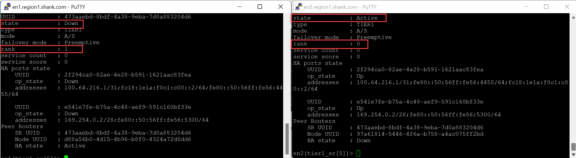
This image below is the same output with Standby Relocation disabled.
As you can see, with TEP / data plane failure, the active SR moves to the remaining Edge node, and if standby relocation was enabled, the priority is adjusted accordingly.
Note: at the time of writing this article, when testing on VMware NSX 4.0.1.1, when the Edge with the active SR is failed, the active SR moves to the remaining Edge node. However, the rank is not lowered on the active Edge node, despite having preemption and standby relocation enabled. I will update this article after further investigation, to determine if this is a bug or intended.
What occurs if the same test is performed on an Active-Standby Tier-0 gateway?
Since there is no standby relocation setting on the Tier-0 gateway, once Edge Node 1 is deemed down/offline. The Active SR moves to Edge Node 2, however, the rank does not move and it remains as 0 on Edge Node 1. Once it is brought back online and preempt is enabled, Edge Node 1 takes over as the Active SR.
Maintenance Mode
Utilizing maintenance mode in the NSX Manager UI is another way of administratively shutting down the Edge node. Any active SR that existed on the node will move to one of the remaining active Edge nodes in the cluster. All the scenarios described above would still apply, the difference is the way in which the Edge node is being taken offline.
Unsupported VMware NSX Edge Failure Testing
This section will cover the impacts of disconnecting an Edge VM vNICs to test failover.
Do Not Disconnect a Edge VM’s vNIC
Disconnecting the virtual NICs of an Edge VM is not a valid test, this operation does not cause the TEP interfaces attached to the vNIC to failover. This will in fact cause traffic to be blackholed, this is because the TEP interface’s assigned MAC address is sticky on the VDS port, and disconnecting the vNIC will not cause it to move. The image below shows the vDS port before the vNIC is disconnected.
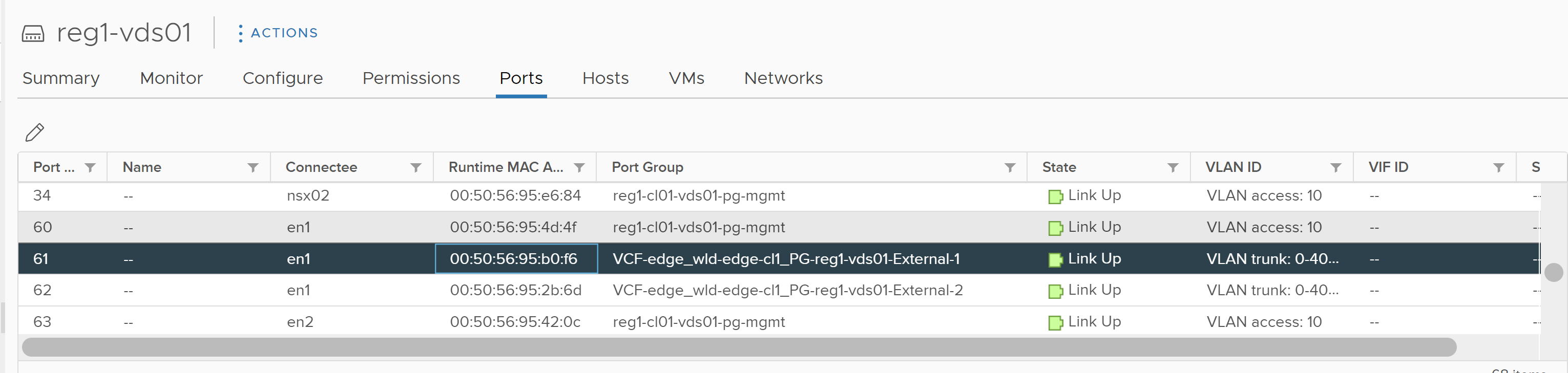
The image below confirms the vNIC on the Edge VM.
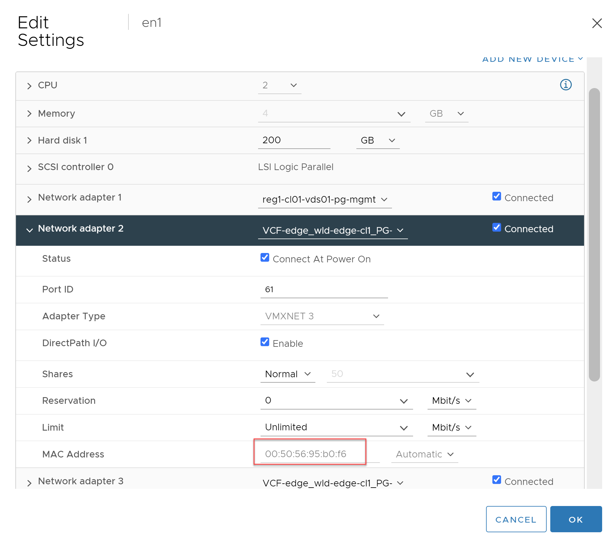
Using the two images above we have been able to identify the correct vNIC on the VM and can see the link status is up.
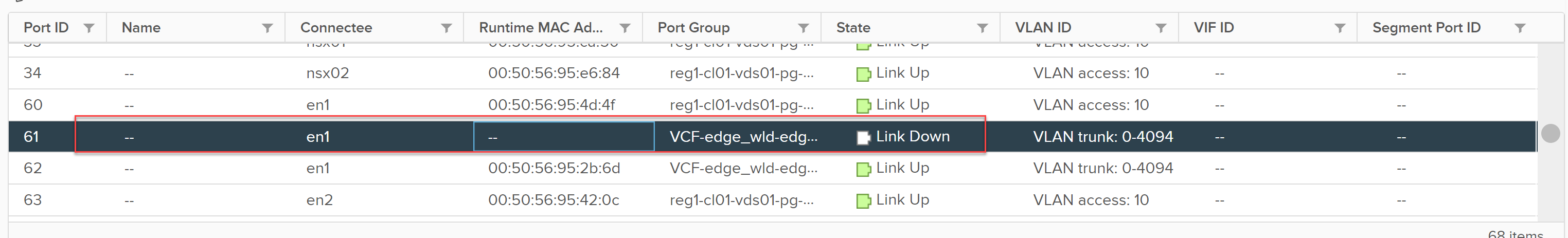
Disconnecting the VM’s vNIC moves the port status to link down, however, the associated MAC address does not move.
Why does this matter, even if the TEP interfaces are logical interfaces on the Edge node?
Because the MAC address that is represented on the vDS port is actually the MAC address assigned to the TEP interface, as can be seen below.
Even if the BFD sessions indicate the tunnel is down to the associated TEP interface, the downstream transport nodes do not update their tables and remove the unreachable TEP. As part of packet forwarding operations in NSX, each packet is hashed and loadbalanced across the available TEP interfaces to the destination. You can see why the ‘down’ TEP interface that disconnected would cause an issue. Upto 50% of the traffic would be hashed/loadbalanced to the TEP from a host transport node, as it thinks its still a valid TEP destination, and subsequently, that traffic will be blackholed. The only way to have the traffic pass after disconnecting the vNIC is to enable promiscuous mode and forged transmits on the uplink vDS portgroup that is still connected, essentially, the portgroup attached and still connected to the Edge Node.
The correct way to test failover of an Edge VM’s NIC and its underlaying TEP is to fail the pNIC of the host transport node, where the Edge VM resides. Performing this operation ensures the teaming and failover configuration of the vDS portgroup that is assigned to the Edge uplink interface is utilized and it moves to the remaining pNIC in the failover settings, which ensures the TEP interface is still active and accessible.
A BareMetal Edge behaves differently, as it has direct access to the pNICs. If a pNIC fails on a BareMetal Edge, the TEP interface will move to the remaining pNIC to ensure it is still accessible.
Summary
The purpose of this article was to provide readers with a deep understanding of the various VMware NSX Edge failure scenarios, and the expected behavior. It is important to understand these scenarios, as no data center has a 100% uptime, being able to predict and determine a failure could save a lot of stress and angst when that inevitable failure occurs.
I have previously covered Service Router placement if you would like to read into that a bit more, and as mentioned, the deeper routing topics are all covered in my book, “NSX-T Logical Routing“.
Keep in mind that when working with BM edges and a Federated setup, you have to connect the pNICs of the BM Edges crossed, see my blogpost on this: (nsx-t version 3.1.2).
https://vronin.nl/nsx-t/design-consideration-for-baremetal-edge-with-4-pnic-in-a-nsx-t-federated-environment/
For sure, however, the failure behavior described in this article typically unaffected by wiring.