
VMware NSX TEP HA; Better Dataplane Resiliency?
Tunnel Endpoints (TEPs) are a fundamental construct in VMware NSX; they are mandatory if overlay networking is being designed and deployed. This article focuses on VMware NSX TEP HA (TEP High Availability for Host Transport Nodes) that was released with VMware NSX 4.1. An overview of TEPs and their importance will be covered prior to dissecting this new feature.
- What are Tunnel Endpoints?
- What is the significance of a TEP?
- TEP Failure Behavior Before VMware NSX 4.1
- Added TEP High Availability in VMware NSX 4.1
- Configuring MultiTEP High Availability
- Testing and Verification
- Summary
What are Tunnel Endpoints?
In its most simplest form, TEPs are a logical interface that are assigned a MAC and IP address. These interfaces exist on VMware NSX Edge Nodes and Host Transport Nodes (hypervisors that are NSX enabled) – noting that they are only required on Host Transport Nodes where overlay routing is being deployed. Without TEPs, GENEVE tunnels would not be instantiated between transport nodes (hosts and edges), and as a result, would not be able to logically route and switch traffic.
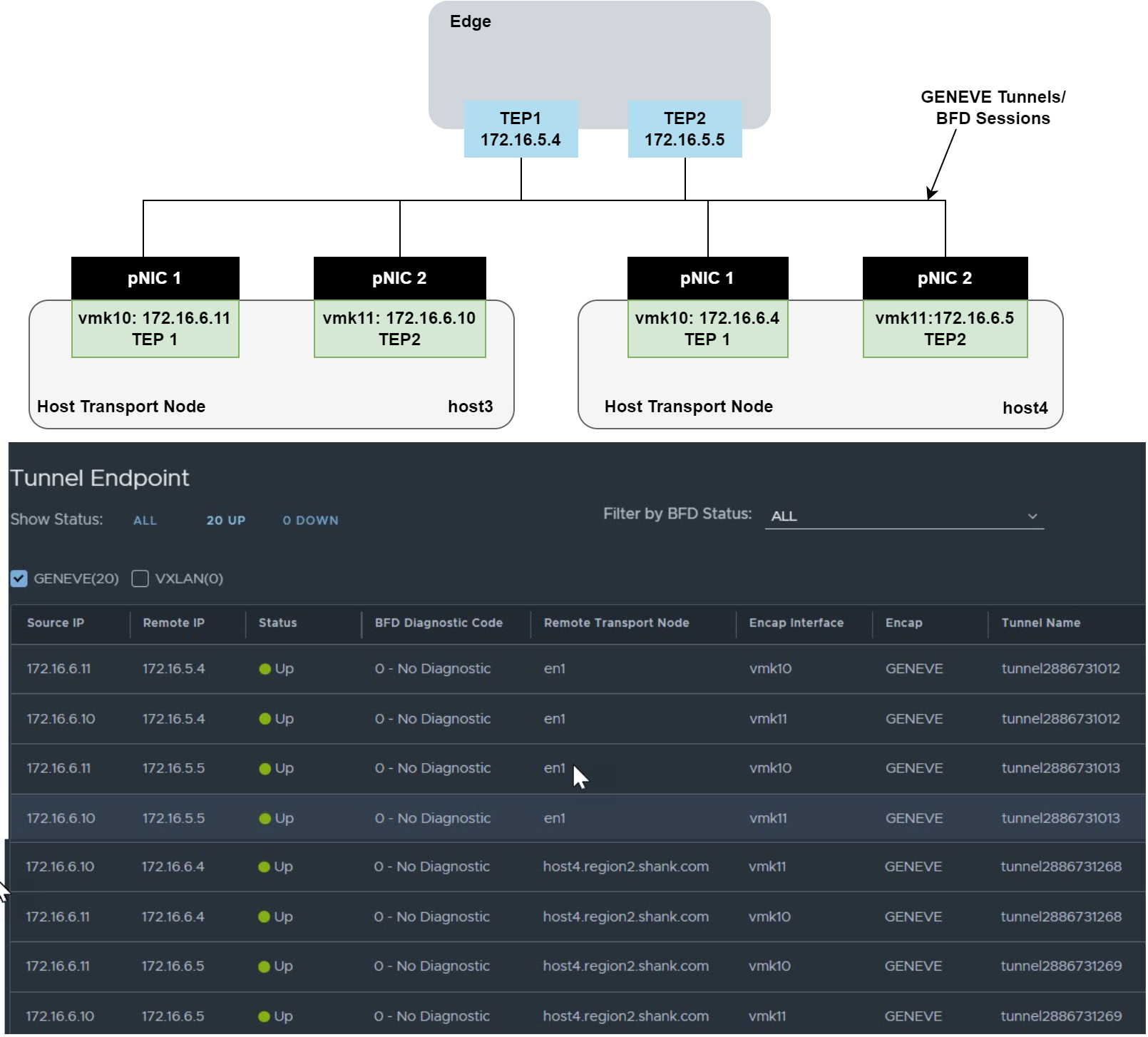
The diagram below is an example of the tunnels that are created between TEP interfaces.
What is the significance of a TEP?
As mentioned earlier, TEPs are required for overlay routing and switching, and the next few images demonstrate how they are used.
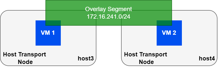
Picture the same two hosts above, each with a VM that is attached to the same overlay segment.
| VM | MAC | IP Address |
| VM 1 | 00:50:56:a3:70:ba | 172.16.241.191 |
| VM 2 | 00:50:56:a3:0f:68 | 172.16.241.127 |
The table shows the IP/MAC mapping for both VMs. The VMs do not care what type of network they reside on, and since they are in the same subnet, will ARP for each other. This article will not cover logical routing in detail, however, my book NSX-T Logical Routing covers this in-depth.
For the sake of this article, we’ll need to go one layer deeper to understand how TEPs play a role in all of this. The following images show the various tables that define the location of VM 1 to the rest of the VMware NSX fabric.
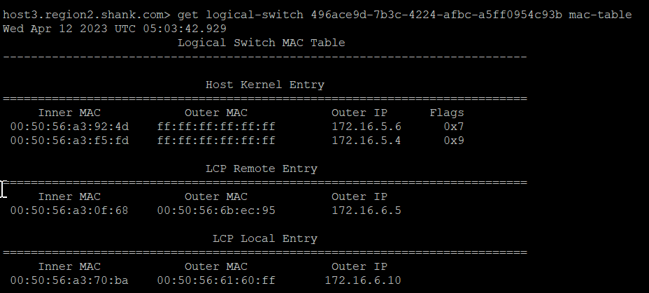
Below is the MAC table of the switch that both VMs are connected to.
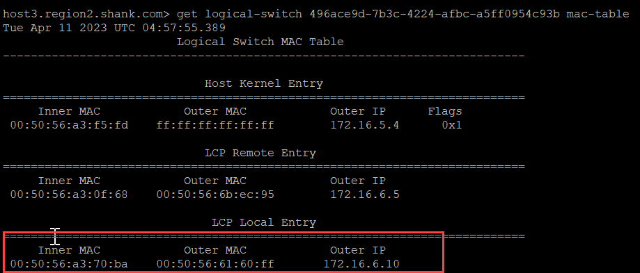
The red box shows the Local Control Plane (LCP) Local Entry, which has an inner MAC (VM1’s MAC), an Outer MAC (which is TEP2’s MAC address), and an Outer IP (TEP2’s IP address).
The image below is the ARP table.
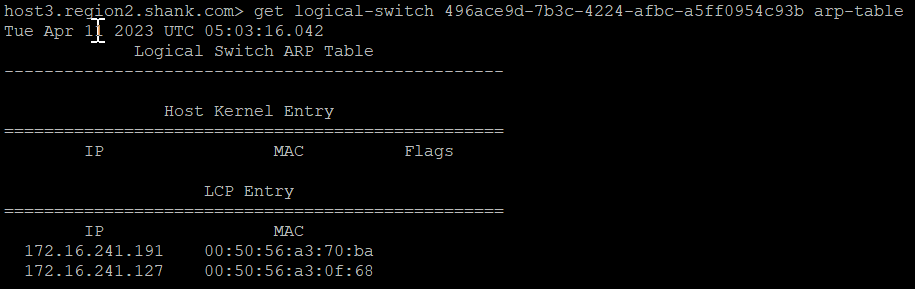
This table shows that the NSX fabric is aware of the VMs and their respective IP and MAC addresses. Using the information from both of these images, we can populate a more complete table.
| VM | MAC | IP Address | TEP MAC | TEP IP | Host |
| VM 1 | 00:50:56:a3:70:ba | 172.16.241.191 | 00:50:56:61:60:ff | 172.16.6.10 | Host 3 |
| VM 2 | 00:50:56:a3:0f:68 | 172.16.241.127 | 00:50:56:6b:ec:95 | 172.16.6.5 | Host 4 |
To summarize, we can see that the VM is associated with a TEP interface (MAC and IP Address), and the packets are routed or switched locally on the host transport node, and simply sent to the destination TEP interface.
Hopefully this section has highlighted why TEP interfaces are crucial to logical routing and switching in NSX.
TEP Failure Behavior Before VMware NSX 4.1
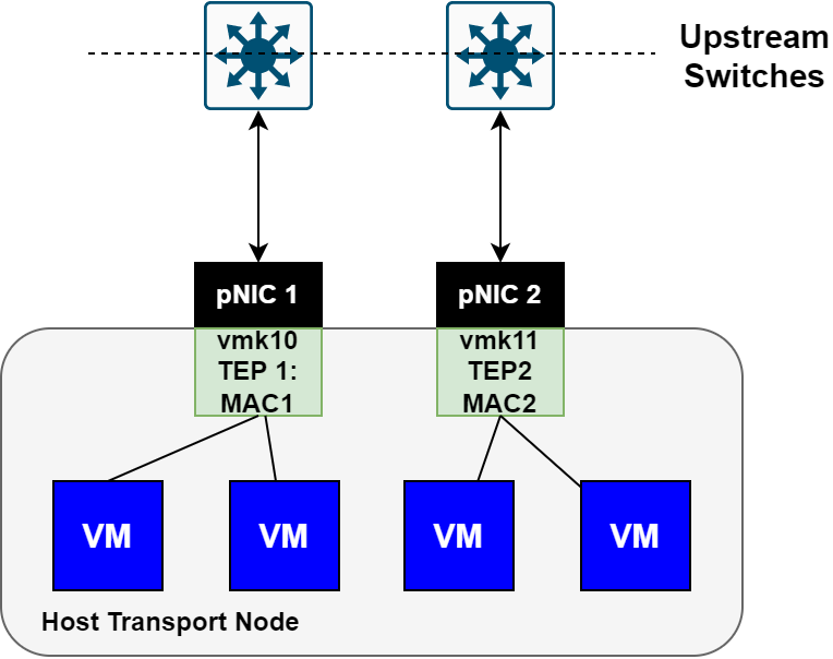
In earlier versions of VMware NSX, the TEP failure behavior was simply a MAC move with a reverse ARP (RARP) to the physical fabric to update forwarding tables. The behavior is highlighted in the images below.
The first image shows a healthy host transport node with both uplinks active and VMs balanced across both TEP interfaces.
The image below is the same node, however, now shown with a failed uplink interface.
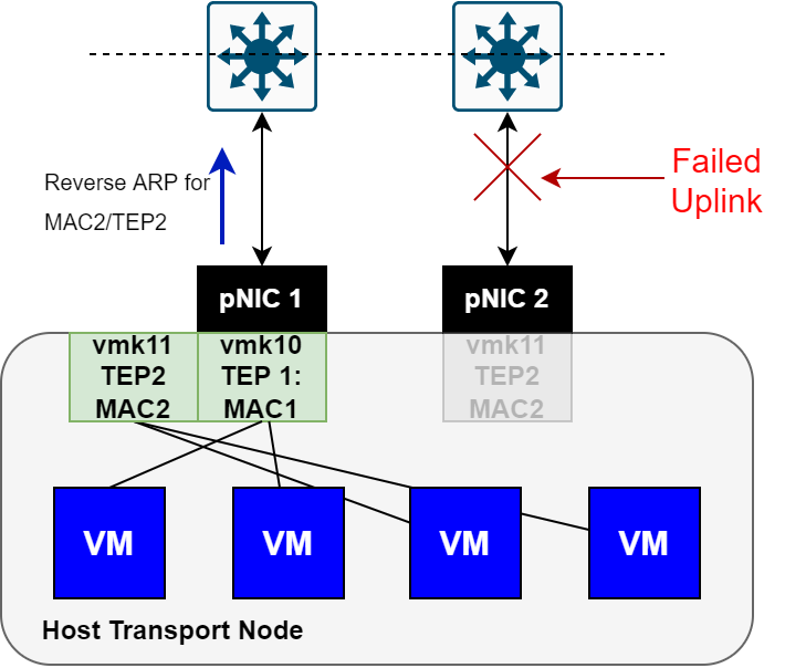
Notice that in the above image, TEP2 moved to the remaining uplink interface, and a Reverse ARP was sent upstream to flush the required tables.
Lets see this in action using Host 3 from earlier.
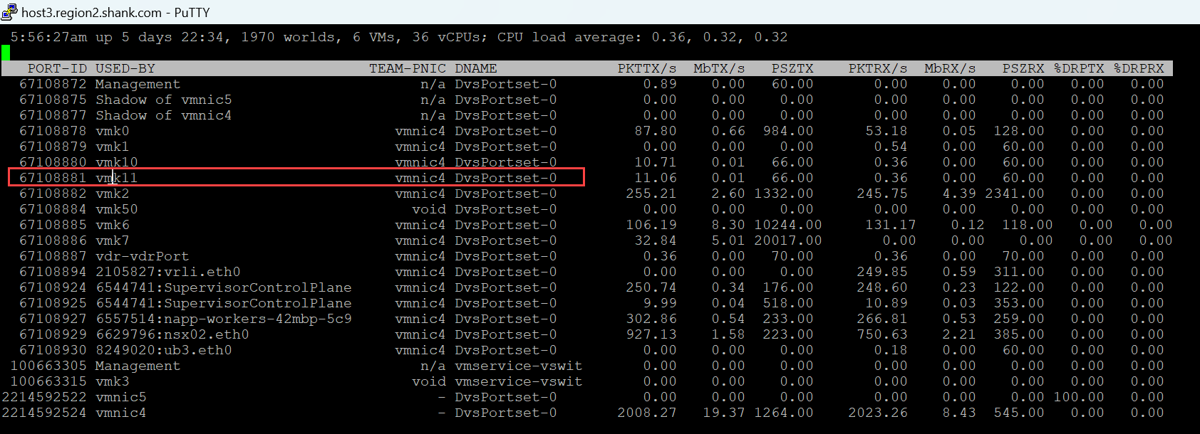
We already know that VM1 was associated with TEP2(VMK11) on Host 3, now all that is required is to identify which physical uplink interface VMK11 is utilizing. There are many ways this can be accomplished, but the easiest and my preferred method is to use CLI. From the host type esxtop, then press n. You will see output similar to the below.
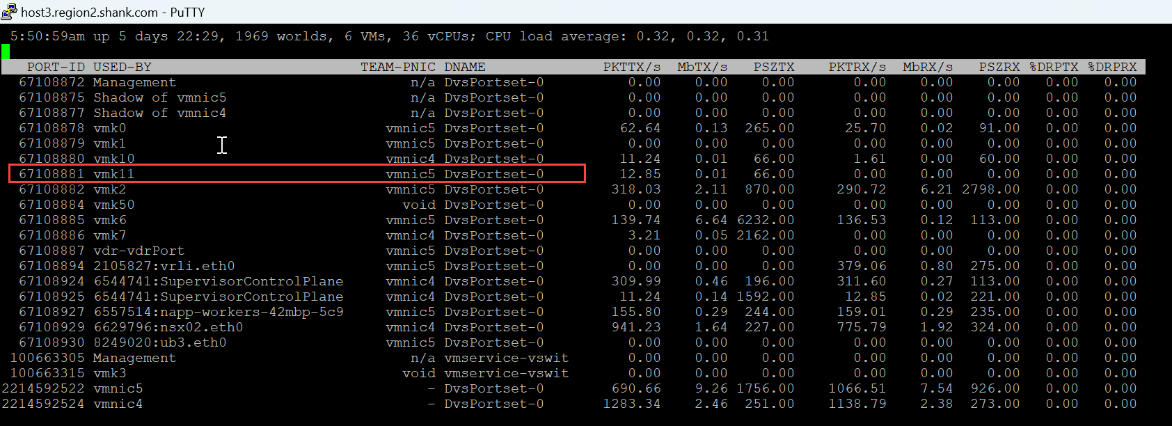
We see that VMK11 is attached to vmnic5, so I will simulate a failure on the upstream port associated with vmnic5.
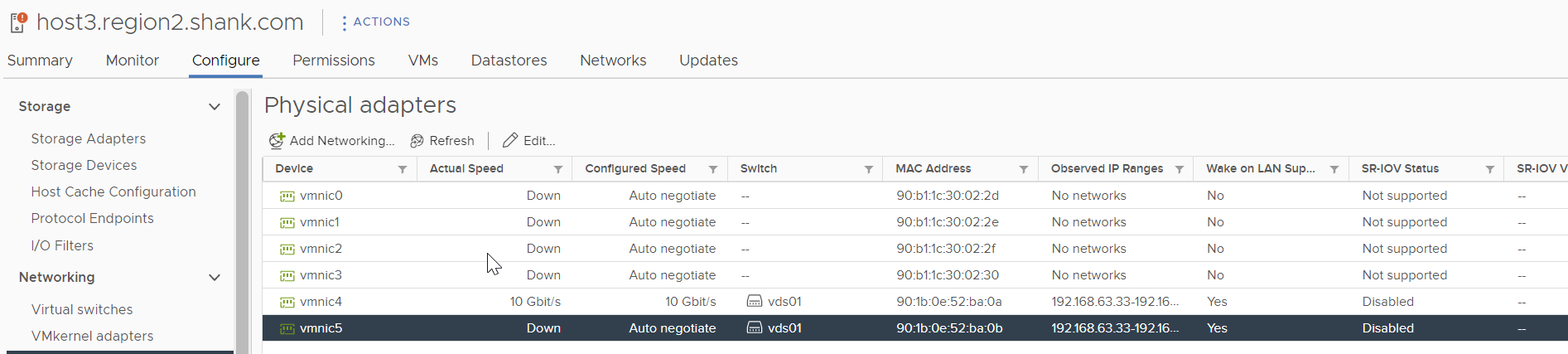
The image below shows that vmnic5 is down.
The output from esxtop shows VMK11 has moved to vmnic4.
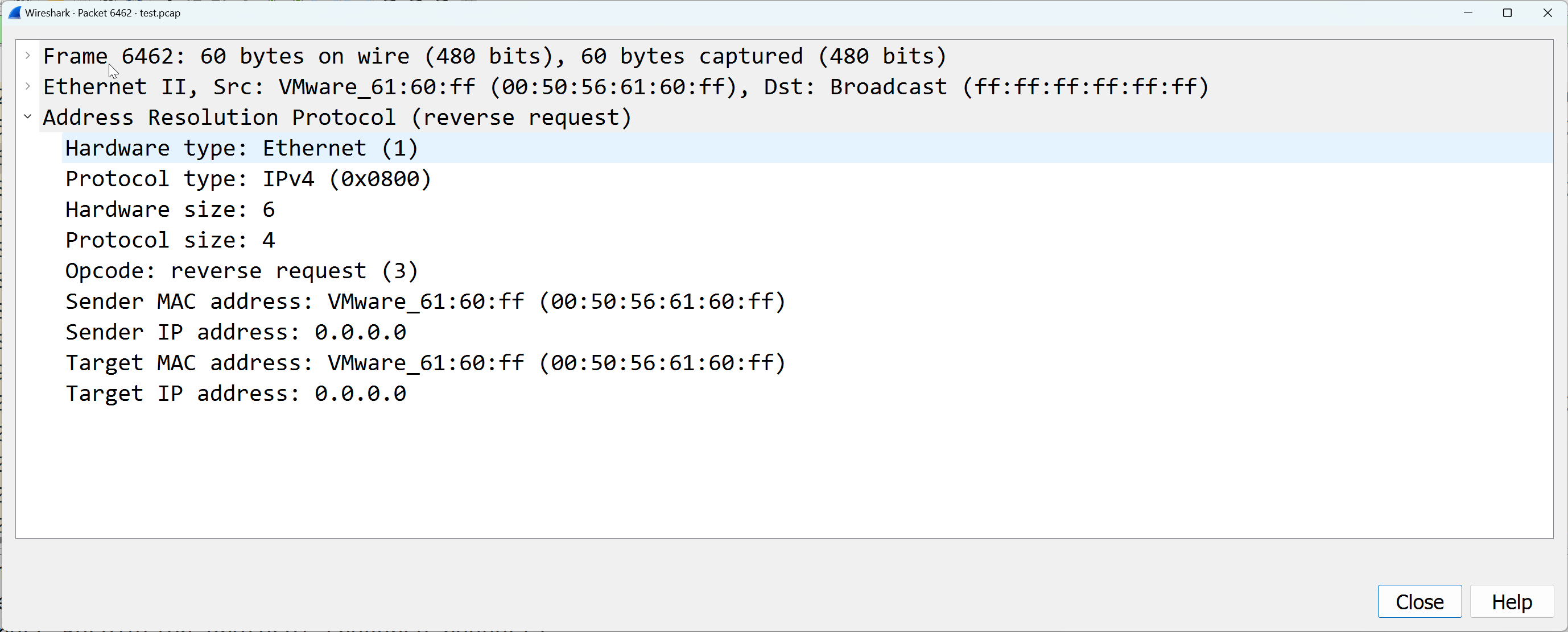
The packet capture below shows the RARP sent out vmnic4 upstream.
NOTE: the MAC moving process is outageless to any workload that is associated to the TEP interface. Once the interface is active again, the TEP interface automatically moves back.
Added TEP High Availability in VMware NSX 4.1
There may be situations where the physical uplink is up and operational, however, packets are not being transmitted. Situations where this could arise may be; upgrade cycles of hardware, VLANs inadvertently being pruned, poor ACL configuration etc.
In efforts to preempt outages caused in these situations, MultiTEP High Availability was released with with VMware NSX 4.1.
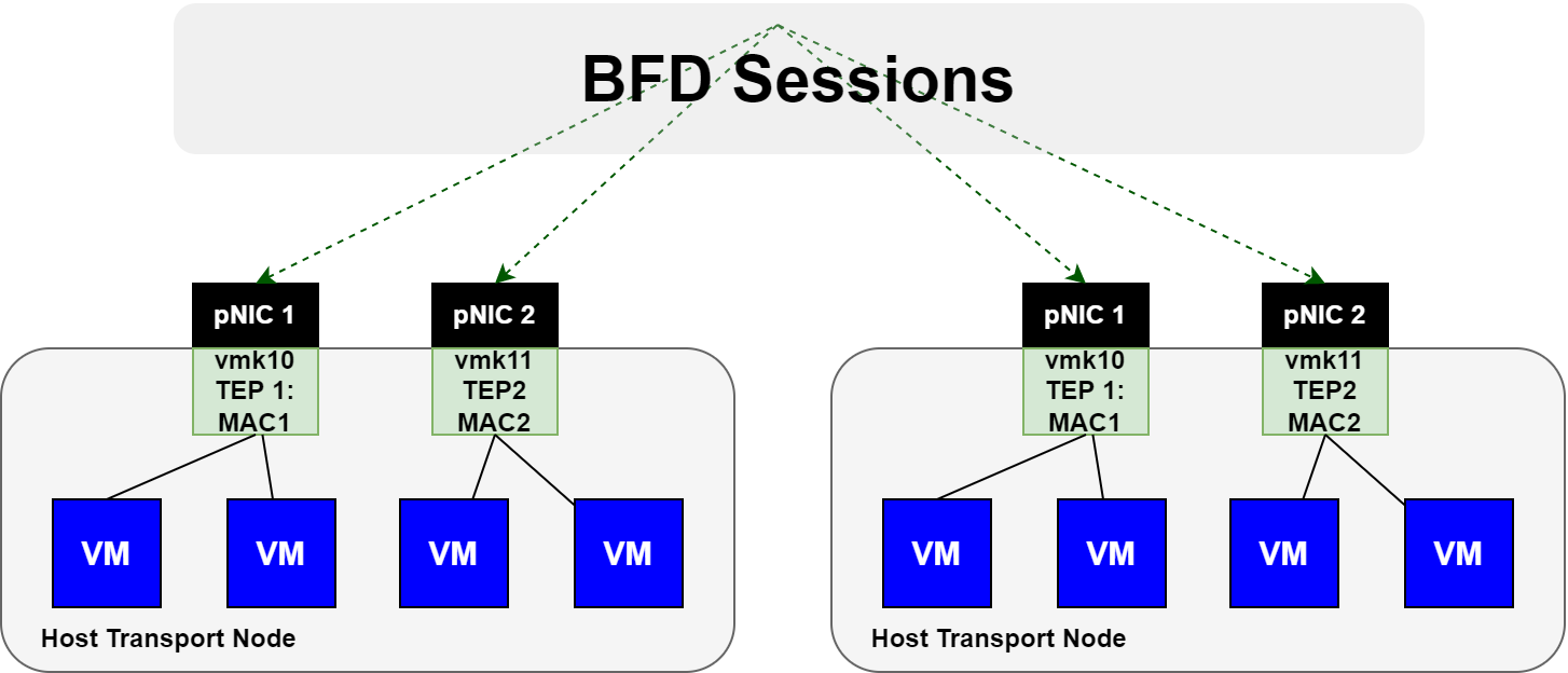
This feature utilizes BFD sessions that are automatically instantiated between each TEP interface. Remember, each GENEVE tunnel between transport node TEP interfaces, has an active BFD session. The image below is an example.
If a TEP interface suddenly loses all BFD sessions to / from it, any VMs that were associated to the TEP interface will move to the remaining TEP interface. Refer to the image below.
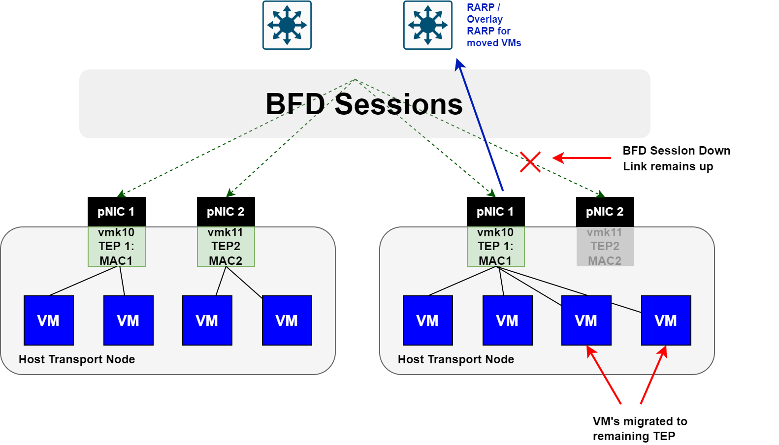
Here you can see that the BFD session is down, however, the link is still up. When this occurs, the TEP interface is declared down and any VMs are moved to the remaining TEP interface.
Keep in mind, this feature requires a day 2 configuration, which will be covered in the coming sections, and this move is not outageless. If you do not have this enabled and one of these situations occur, you would lose connectivity to the VMs, as they would still be attached to the TEP interface that has lost connectivity.
Configuring MultiTEP High Availability
The steps to configure this feature are;
- Create a new VTEP HA Host Switch Profile
- Add the VTEP HA Host Switch Profile to a Transport Node Profile (enables an entire cluster at a time)
- Add the VTEP HA Host Switch Profile to a Transport Node individually (not required if step 2 is performed)
Creating a VTEP HA Host Switch Profile
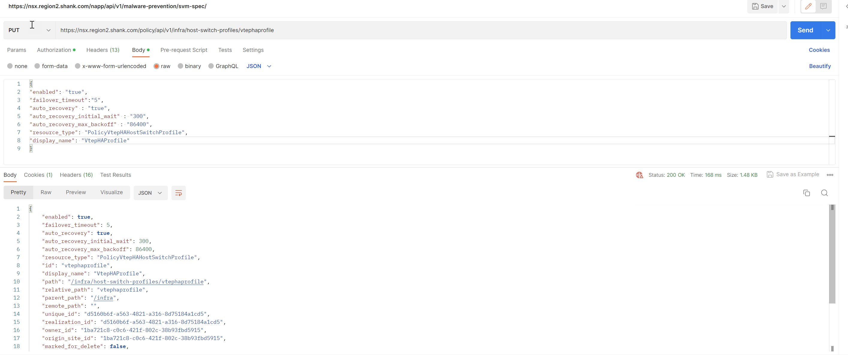
Use a PUT method to create the VTEP HA Profile. The fields that are set specify different behaviors and can be found here.
curl --location --request PUT 'https://nsx.region2.shank.com/policy/api/v1/infra/host-switch-profiles/vtephaprofile' \
--header 'Content-Type: application/json'
--data '{
"enabled": "true",
"failover_timeout":"5",
"auto_recovery" : "true",
"auto_recovery_initial_wait" : "300",
"auto_recovery_max_backoff" : "86400",
"resource_type": "PolicyVtepHAHostSwitchProfile",
"display_name": "VtepHAProfile"
}'
This creates a VTEP HA host switch profile.
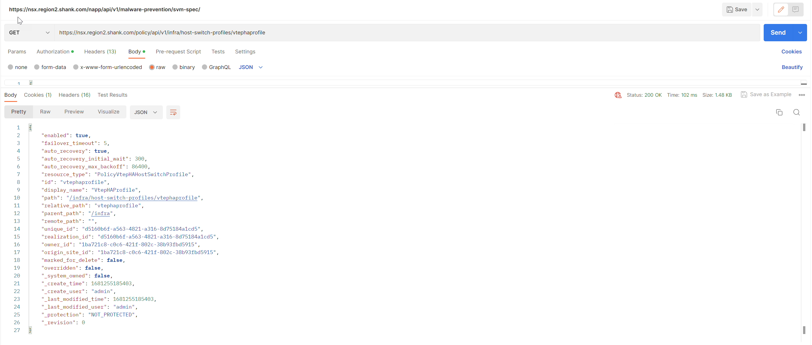
Issue a GET to ensure it has been created.
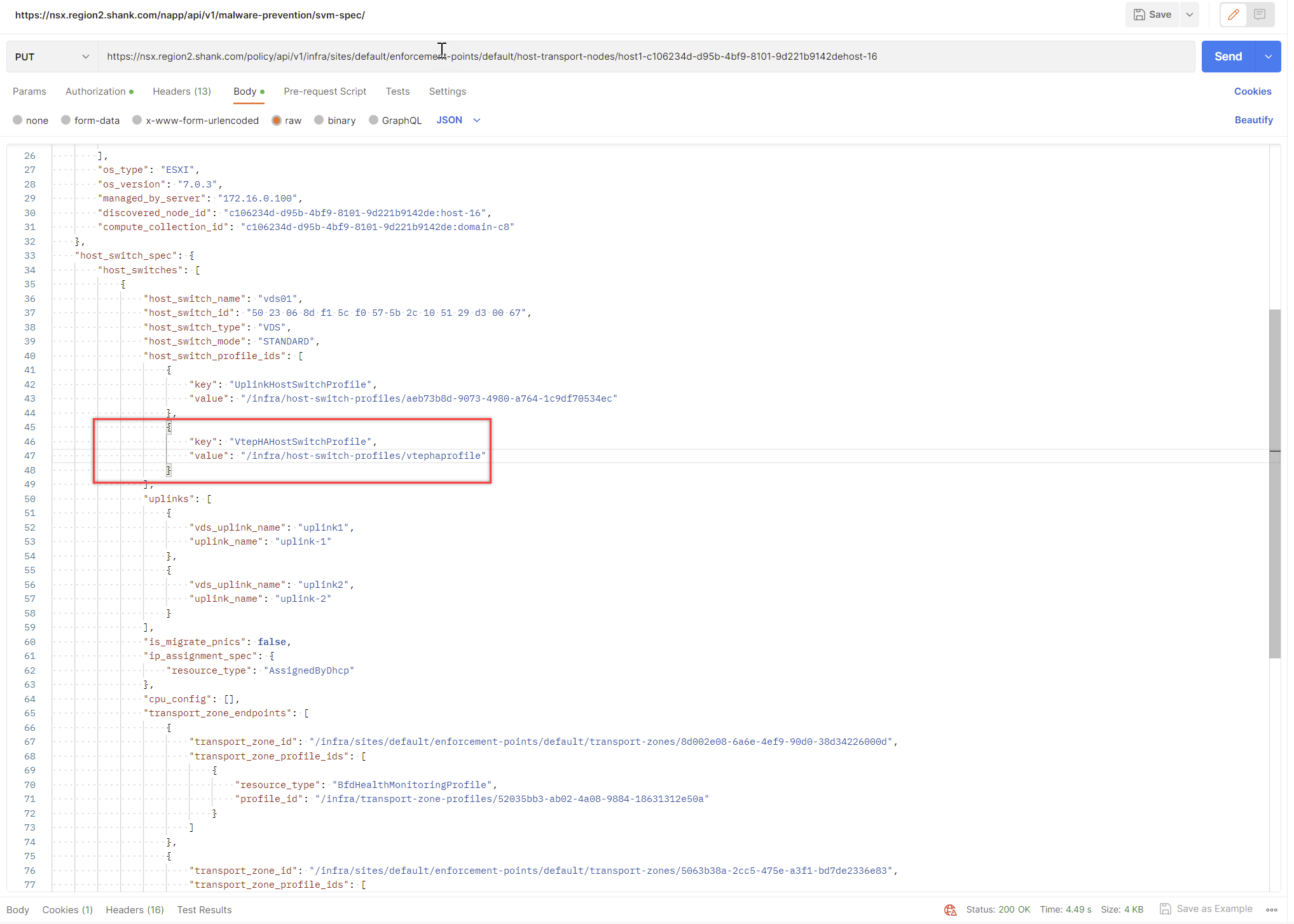
Attach VTEP HA Host Switch Profile to a Transport Node Profile
You can either create a new Transport Node Profile and attach the VTEP HA host switch profile to it OR update an existing Transport Node Profile. I will create a new Transport Node Profile.
Create a Transport Node Profile
Login to NSX -> System -> Fabric -> Hosts -> Transport Node Profiles -> Add Transport Node Profile.
Enter a name, click on Set Host Switch.
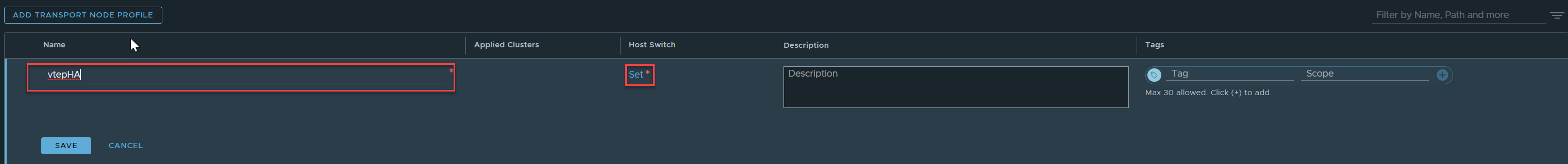
Click on Add Host Switch.
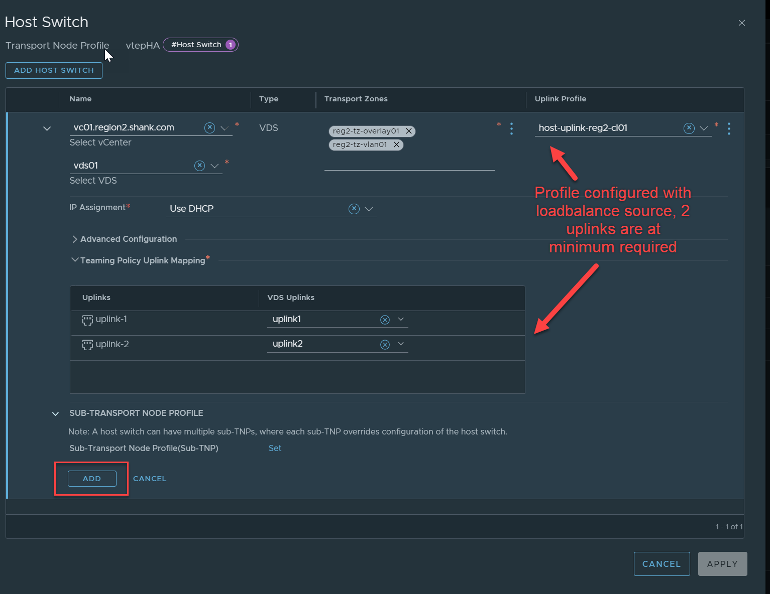
Make sure you save the profile once it is configured.
Option 1: Attach the VTEP HA Profile to the Transport Node Profile
Once both profiles have been configured, you must associate the VTEP HA profile to the Transport Node Profile, which will then apply to the hosts once attached in NSX.
Identify the Transport Node Profile with API
Send a GET request to https://nsxfqdn/policy/api/v1/infra/host-transport-node-profiles/.
It will list all transport node profiles that exist, along with their ID’s.
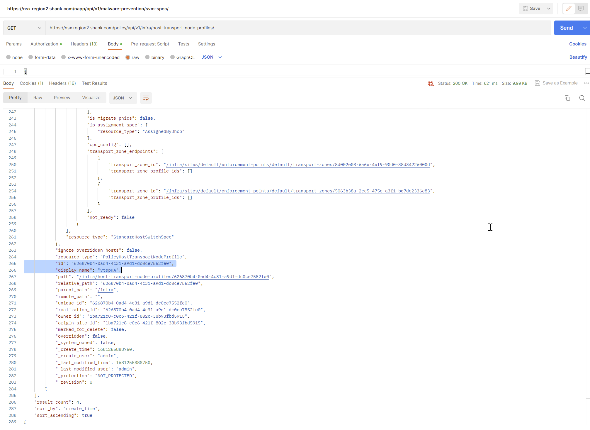
To make things easier, I will now issue the same GET request, this time with the ID highlighted on the end.
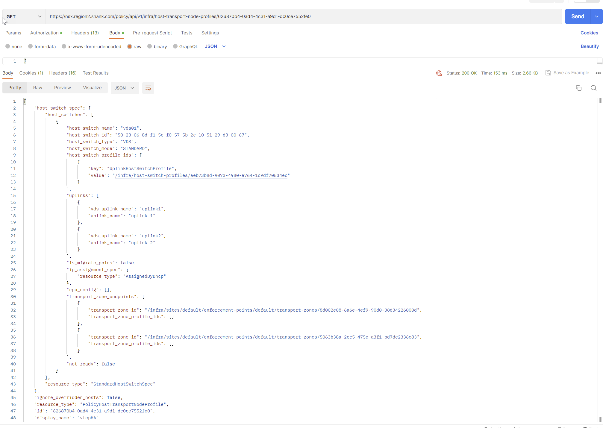
Copy everything in the result, change the request type to PUT and paste the contents into the body. Update the section below, making sure the value is the relative path of your VTEP HA profile. If you are uncertain of the relative path, you can issue a GET request to https://nsxfqdn/policy/api/v1/infra/host-switch-profiles/vtephaprofile.
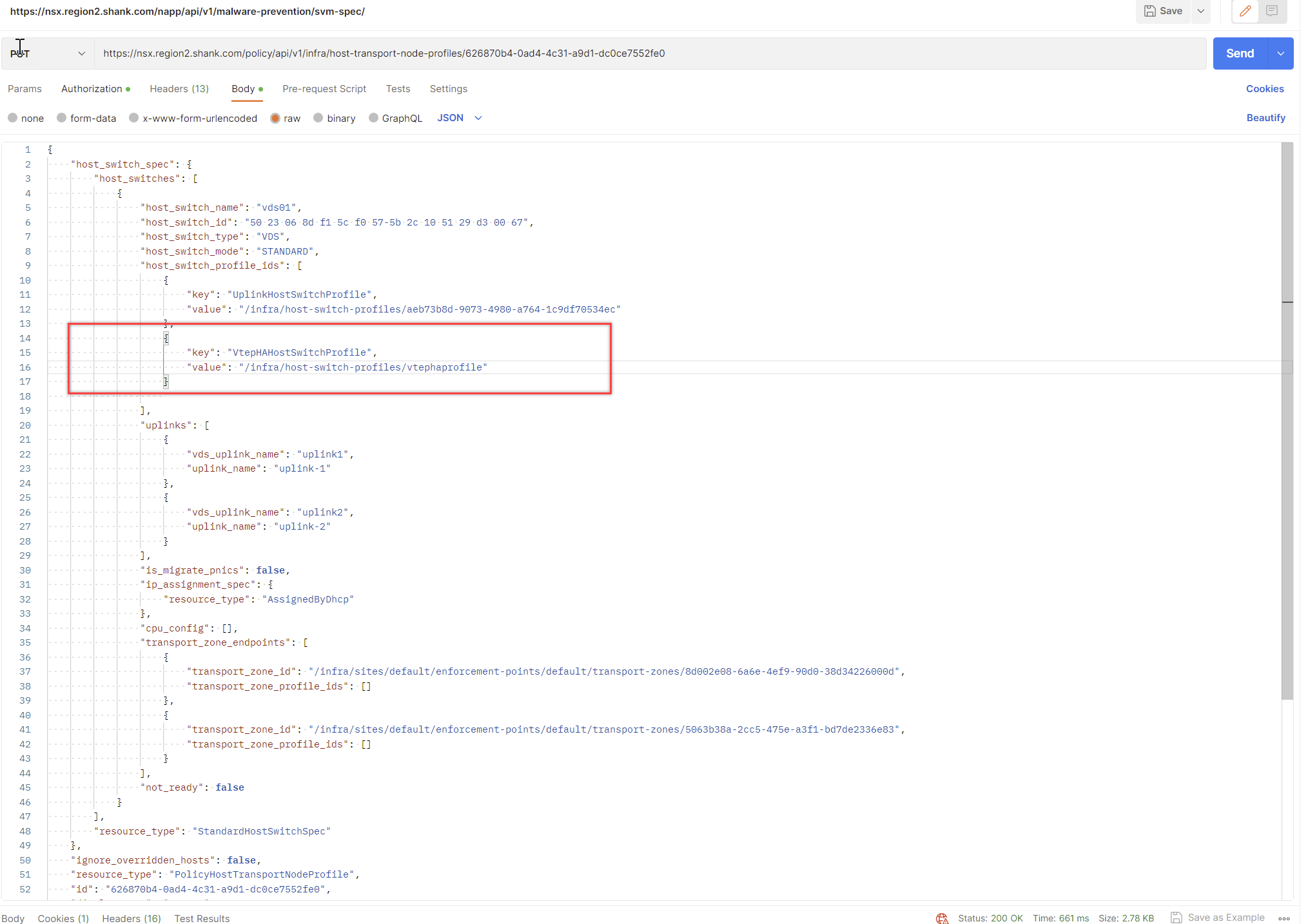
                    {
                        "key": "VtepHaHostSwitchProfile",
                        "value": "/infra/host-switch-profiles/vtephaprofile"
                    }
You should receive a 200 Ok, indicating that the request was successful.
Option 2: Attach the VTEP HA Profile to an Individual Node
Assuming you have already created the VTEP HA profile, issue a GET to https://nsxfqdn/policy/api/v1/infra/sites/default/enforcement-points/default/host-transport-nodes/ and identify the UUID of the host you want to attach the profile to.
Repeat this process, this time with the UUID of a host on the end of the request.
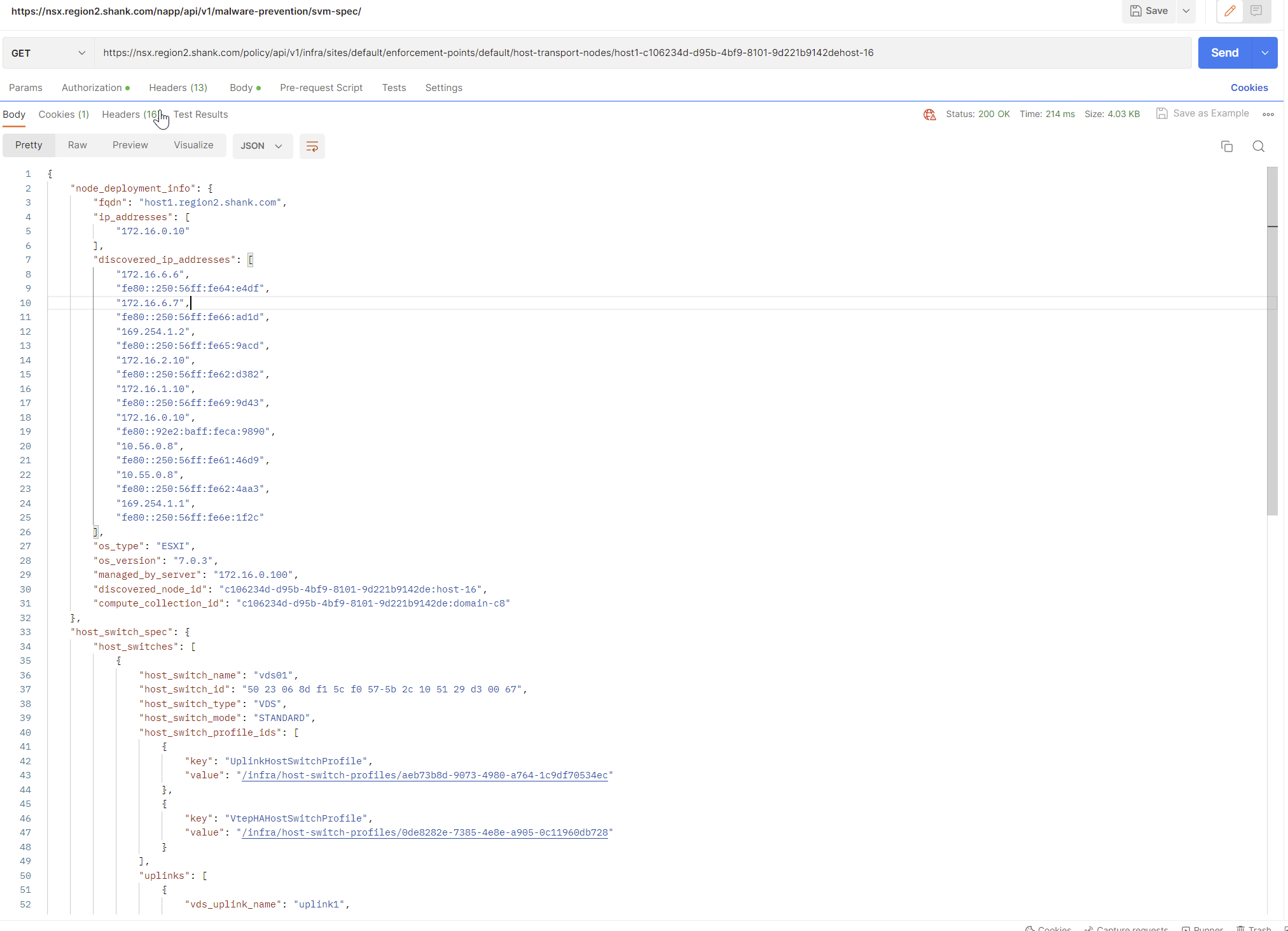
Copy the contents into the body and change the request to PUT, you should receive a 200 Ok if it was successful.
At this point you can re-issue the GET request to ensure the profile was correctly associated with the transport node.
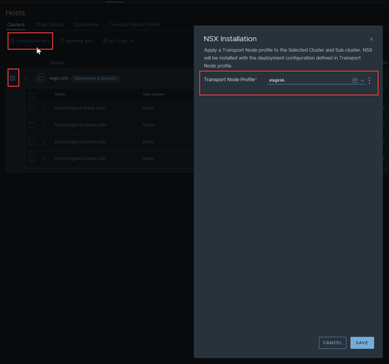
Attaching the Transport Node Profile
In NSX, navigate to System -> Fabric -> Hosts – Clusters, attach the Transport Node Profile to the cluster.
Verify VTEP HA is enabled
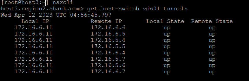
SSH onto any of the nodes in the cluster using the root account and issue the command in the image below, “net-vdl2 -F GET tepha -s vds01 (replace vds01 with your VDS name)

The feature will be disabled if the previous steps were not followed.
Testing and Verification
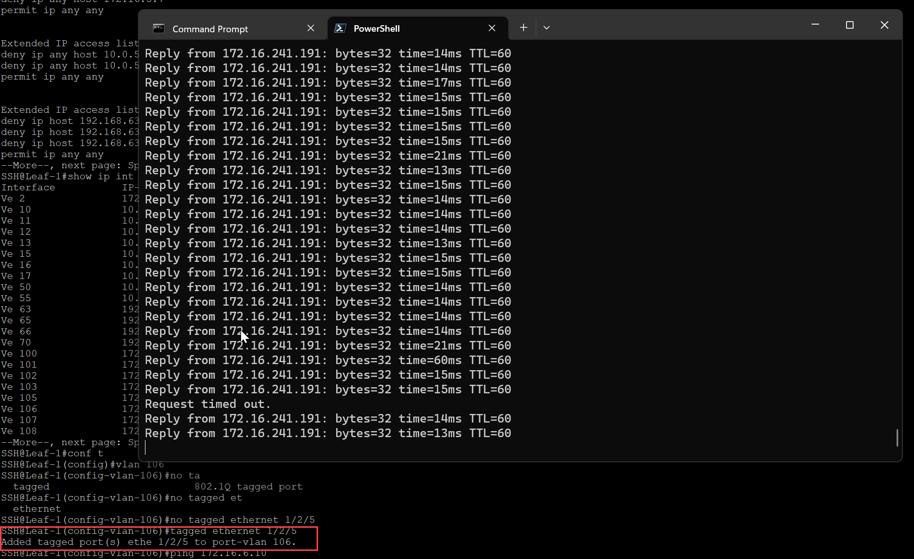
To test this feature, I will prune the TEP VLAN from the upstream switch port that VM 1/TEP and host uplink are associated to, this will drop all BFD sessions and should trigger the VM to failover to the remaining TEP.
First open a ping command to the VM.
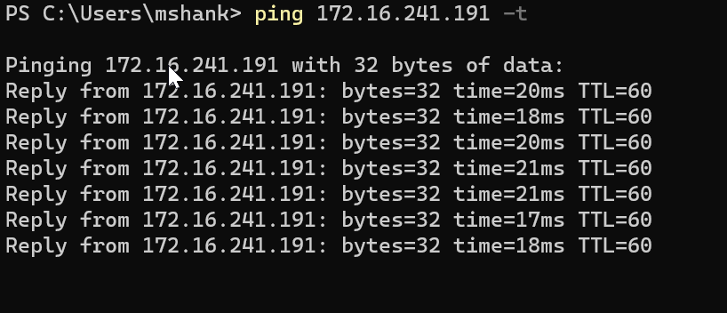
Prune the TEP VLAN from the switch interface that is connected downstream to the host.

BFD-Sessions should drop from vmk11 (172.16.6.10).
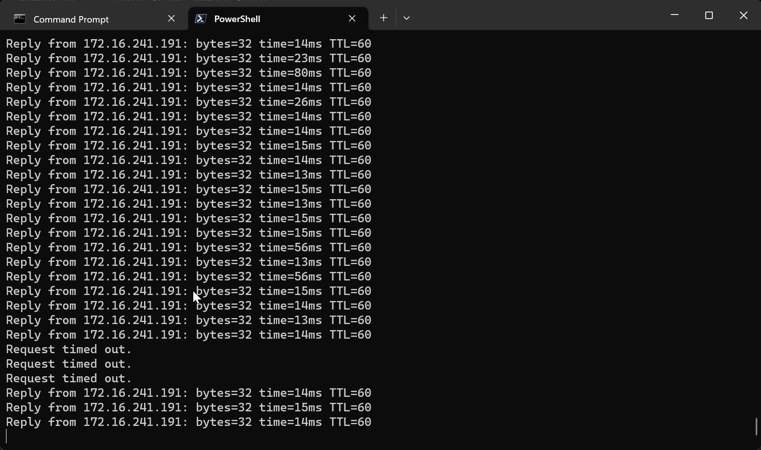
Notice there was a slight outage, this occurs during the process of re-associating the VM with the healthy TEP interface on the host.
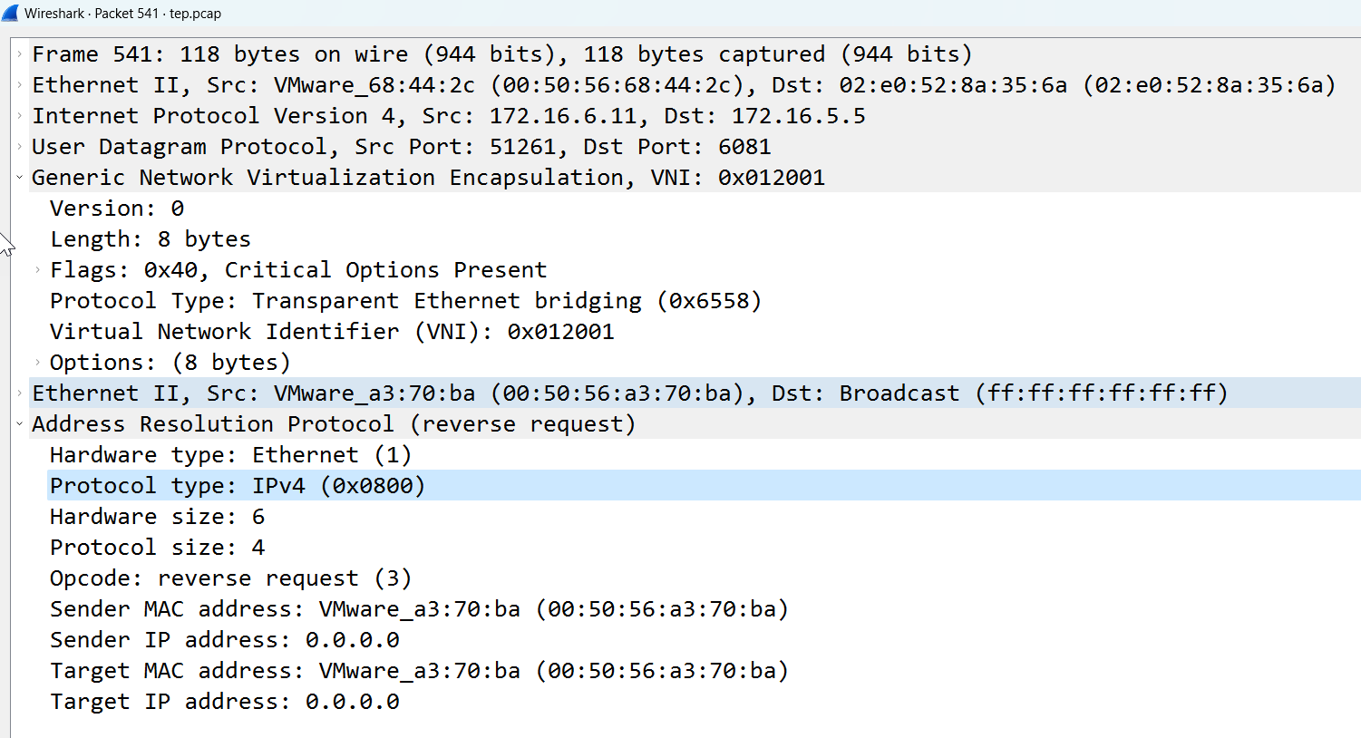
Notice, in the above image, there are no tunnels to the local IP 172.16.6.10. In the packet capture below, we can see another RARP, this time a GENEVE (overlay) RARP with the MAC address of VM 1. Remember in the previous scenario, this was a standard RARP.
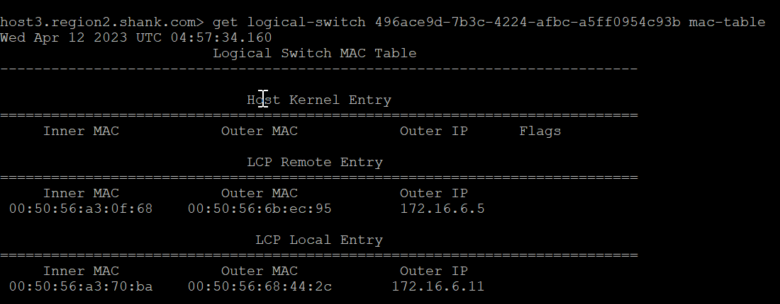
The MAC table on the host verifies that the outer MAC and IP address have changed to the remaining TEP interface.
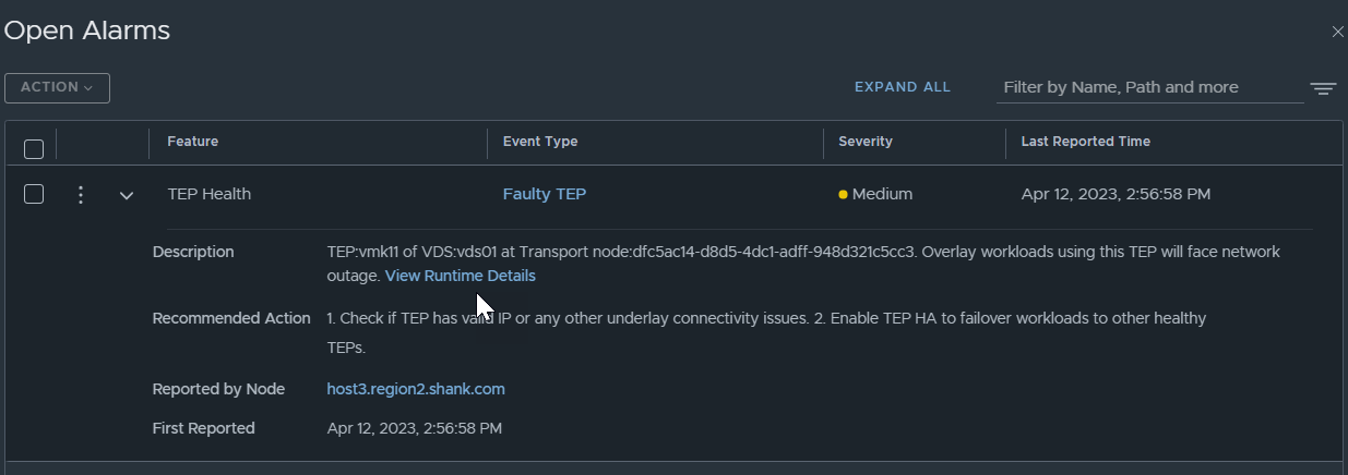
If a TEP fails, there are also alarms created as part of the process, to make it easier for administrators to be aware of the faulty TEP.
Since auto-recover was enabled in the VTEP HA profile, allowing the VLAN on the interface means the VM will be recovered back to VMK11, notice, there is a slight outage again.
The VM has moved back to the original TEP interface.
Once the TEP interface is reinstated, alarms are automatically cleared. If you want to manually failback rather than have it be automated to avoid any outage, in the VTEP profile, ensure you set auto-recover to false. The manual process can be found here.
Summary
Whilst this new feature may not be required all that often, it is a step in the right direction. I have personally seen situations where this could occur, even if it is due to poor house-keeping. It’s also important to note that this new HA feature is not intended to replace the MAC move method. They can both be in operation at the same time.
I didn’t quite get the purpose of encapsulated RARP at the time of TEP change. I’ve always thought that guest MAC to host TEP mapping is mediated by NSX control plane and hence the transport nodes do not have to learn this from data plane directly as in some other overlay schemas. But that RARP actually suggests that there is some learning happening from the data plane cos the RARP is flooded to every node taking part in the logical switch within the transport zone – so they can see that a-ha this guest MAC is now bound to that TEP IP – let’s update tables accordingly.
Each node also has an LCP agent, so this is a quick mechanism for every node to be updated as well as the CCP. After which the CCP maintains the tables for the environment.